AUDIO AND VISUAL SYSTEM(for Radio and Display Type), Diagnostic DTC:B158F
| DTC Code | DTC Name |
|---|---|
| B158F | AV Signal Stoppage (Low Battery Voltage) |
DESCRIPTION
This DTC is stored when a video or audio signal is interrupted due to battery voltage input to the radio and display receiver assembly dropping temporarily.
| DTC No. | Detection Item | DTC Detection Condition | Trouble Area |
|---|---|---|---|
| B158F | AV Signal Stoppage (Low Battery Voltage) | A video or audio signal is interrupted when the battery voltage drops |
|
WIRING DIAGRAM
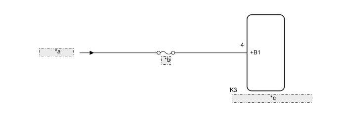
| *a | from Battery |
| *b | TV |
| *c | Radio and Display Receiver Assembly |
CAUTION / NOTICE / HINT
Note
-
Depending on the parts that are replaced during vehicle inspection or maintenance, performing initialization, registration or calibration may be needed. Refer to Precaution for Audio and Visual System.
-
When replacing the radio and display receiver assembly, always replace it with a new one. If a radio and display receiver assembly which was installed to another vehicle is used, the following may occur:
-
A communication malfunction DTC may be stored.
-
The radio and display receiver assembly may not operate normally.
-
Inspect the fuses for circuits related to this system before performing the following procedure.
PROCEDURE
-
CHECK VEHICLE SIGNAL (OPERATION CHECK)
-

Enter the "Vehicle Signal Check Mode" screen. Refer to Check Vehicle Signal in Operation Check.
-
Measure the battery voltage.
Standard Voltage 11 to 14 V Tech Tips
This display is updated once per second.
Result Proceed to OK NG
NG 
CHECK HARNESS AND CONNECTOR (RADIO AND DISPLAY RECEIVER ASSEMBLY POWER SOURCE) Click here
OK 
-
-
CHECK DTC
-
Clear the DTCs.
Body Electrical > Navigation System > Clear DTCs -
Recheck for DTCs and check that no DTCs are output.
Body Electrical > Navigation System > Trouble CodesOK No DTCs are output. Result Proceed to OK NG
OK 
END
NG
REPLACE RADIO AND DISPLAY RECEIVER ASSEMBLY Click here
-
-
CHECK HARNESS AND CONNECTOR (RADIO AND DISPLAY RECEIVER ASSEMBLY POWER SOURCE)
-
Disconnect the K3 radio and display receiver assembly connector.
-
Measure the voltage according to the value(s) in the table below.
Standard Voltage Tester Connection Condition Specified Condition K3-4 (+B1) - Body ground Always 11 to 14 V Result Proceed to OK NG
OK
REPLACE RADIO AND DISPLAY RECEIVER ASSEMBLY Click here
NG
REPAIR OR REPLACE HARNESS OR CONNECTOR
-