ROOF HEADLINING REASSEMBLY
PROCEDURE
INSTALL NO. 4 ROOF HEADLINING SUPPORT (w/ Roof Headlining Support, w/ Sliding Roof)
-

Marking

Peeling Paper
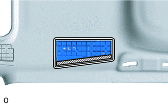
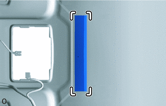
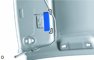
Align the No. 4 roof headlining support with the marking on the roof headlining and install the No.4 roof headlining support to the position shown inthe illustration using adhesive or double-sided tape.
Note:If replacing a new No. 4 roof headlining support:
At this time, do not remove the peeling paper from the No. 4 roof headlining support.
-
INSTALL NO. 3 ROOF HEADLINING SUPPORT (w/ Roof Headlining Support, w/ Sliding Roof)
Tip:Use the same procedure described for the No. 4 roof headlining support.
INSTALL ROOF HEADLINING SUPPORT (w/ Roof Headlining Support)
-
Marking
w/o Sliding Roof:
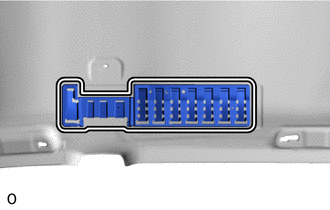
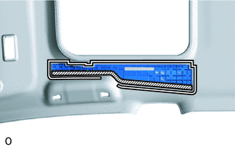
Align the No. 2 roof headlining support with the marking on the roof headlining and install the No.2 roof headlining support to the position shown in the illustration using adhesive or double-sided tape.
-
Marking
Peeling Paper
w/ Sliding Roof:
Align the No. 2 roof headlining support with the marking on the roof headlining and install the No.2 roof headlining support to the position shown in the illustration using adhesive or double-sided tape.
Note:If replacing a new No. 2 roof headlining support:
At this time, do not remove the peeling paper from the No. 2 roof headlining support.
-
INSTALL NO. 2 ROOF HEADLINING SUPPORT (w/ Roof Headlining Support)
Tip:Use the same procedure described for the No. 2 roof headlining support.
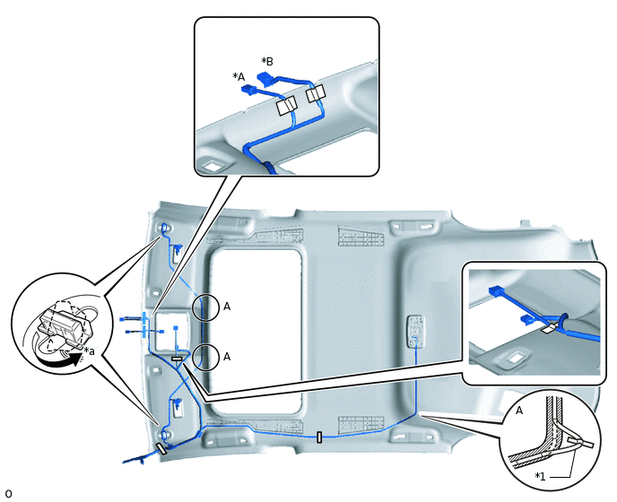
INSTALL NO. 2 ANTENNA CORD SUB-ASSEMBLY
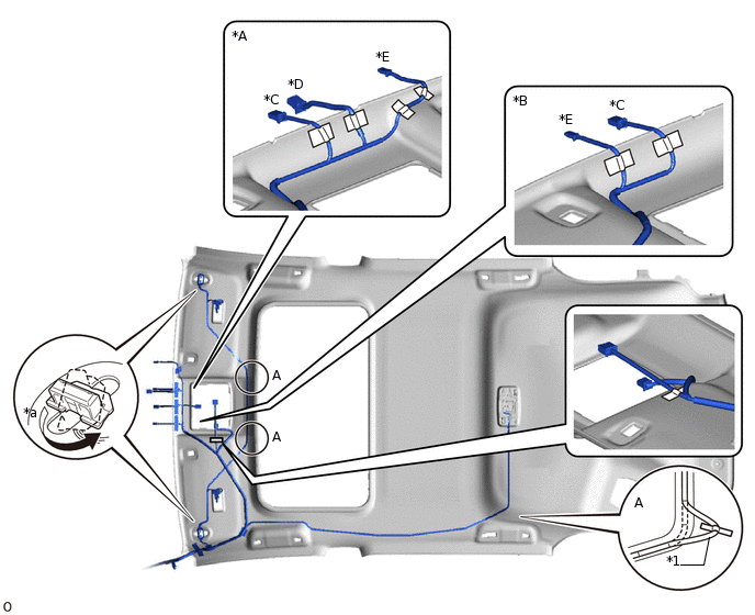
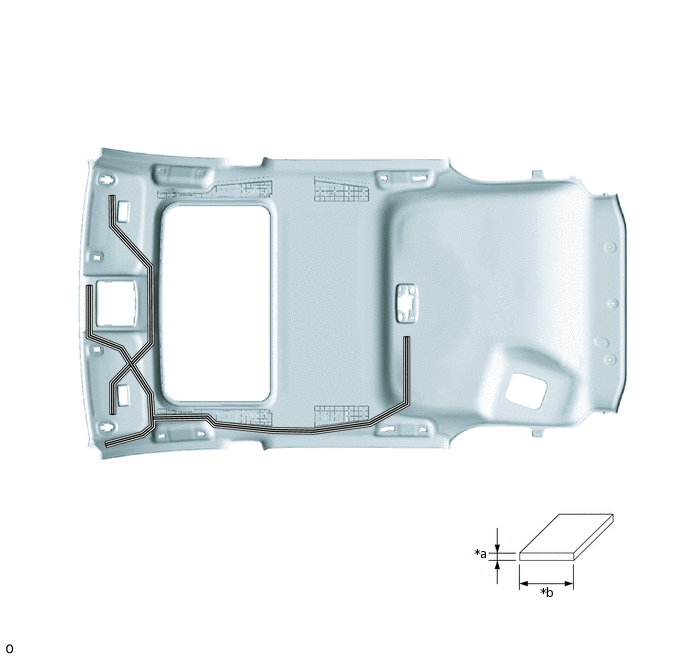
INSTALL NO. 1 ROOF WIRE
w/o Roof Headlining Support, w/o Sliding Roof:
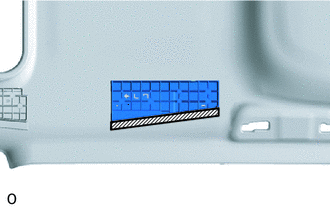
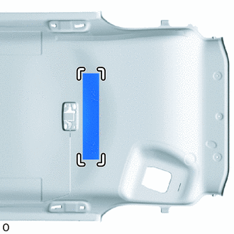
Apply new double-sided tape as shown in the illustration.
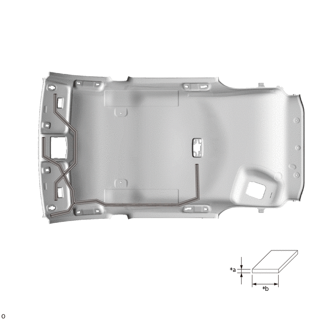
*a
1 mm (0.0394 in.)
*b
15 mm (0.590 in.)
Double-sided Tape
-
-
Attach the No. 1 roof wire to the double-sided tape.
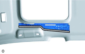
Apply new one-sided tape.
Turn the 2 connectors approximately 90° clockwise to connect them.
If any slack forms, take up the slack in the areas A shown in the illustration.
Note:Secure any wire that protrudes from the double-sided tape with one-sided tape.
*A
for LHD
*B
for RHD
*C
w/ EC Mirror
*D
w/ Lane Departure Alert System
*E
w/ Rain Sensor
-
-
*1
No. 1 Roof Wire
-
-
*a
90°
-
-
One-sided Tape
Double-sided Tape
Check that the No. 1 roof wire is not twisted, raised, or protruding in any way.
w/ Roof Headlining Support, w/o Sliding Roof:
Apply new double-sided tape as shown in the illustration.
*a
1 mm (0.0394 in.)
*b
15 mm (0.590 in.)
Double-sided Tape
-
-
Attach the No. 1 roof wire to the double-sided tape.
Apply new one-sided tape.
Turn the 2 connectors approximately 90° clockwise to connect them.
If any slack forms, take up the slack in the areas A shown in the illustration.
Note:Secure any wire that protrudes from the double-sided tape with one-sided tape.
*A
w/ EC Mirror
*B
w/ Lane Departure Alert System
*1
No. 1 Roof Wire
-
-
*a
90°
-
-
One-sided Tape
Double-sided Tape
Check that the No. 1 roof wire is not twisted, raised, or protruding in any way.
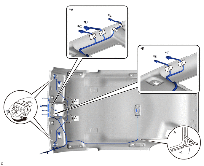
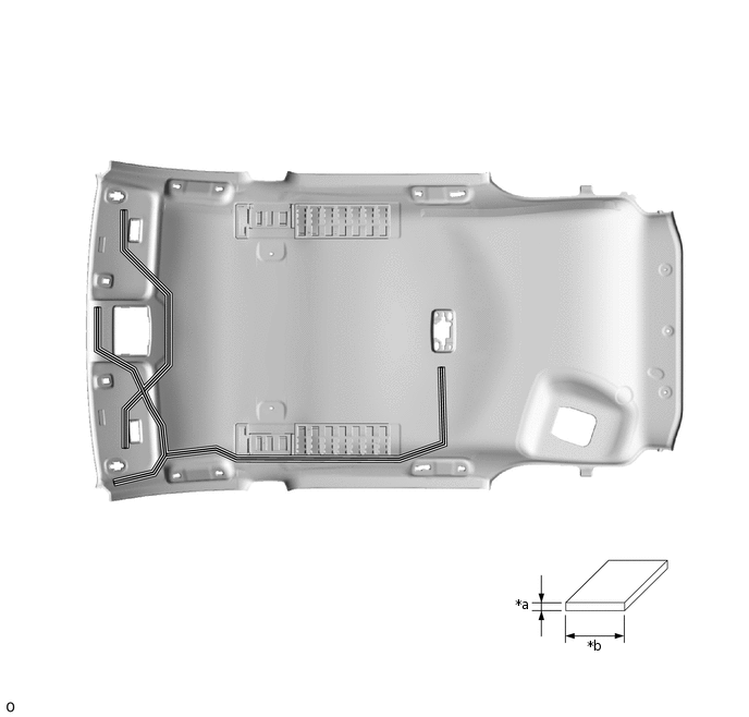
w/o Roof Headlining Support, w/ Sliding Roof:
Apply new double-sided tape as shown in the illustration.
*a
1 mm (0.0394 in.)
*b
15 mm (0.590 in.)
Double-sided Tape
-
-
Attach the No. 1 roof wire to the double-sided tape.
Apply new one-sided tape.
Turn the 2 connectors approximately 90° clockwise to connect them.
If any slack forms, take up the slack in the areas A shown in the illustration.
Note:Secure any wire that protrudes from the double-sided tape with one-sided tape.
*A
for LHD
*B
for RHD
*C
w/ EC Mirror
*D
w/ Lane Departure Alert System
*E
w/ Rain Sensor
-
-
*1
No. 1 Roof Wire
-
-
*a
90°
-
-
One-sided Tape
Double-sided Tape
Check that the No. 1 roof wire is not twisted, raised, or protruding in any way.
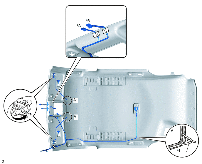
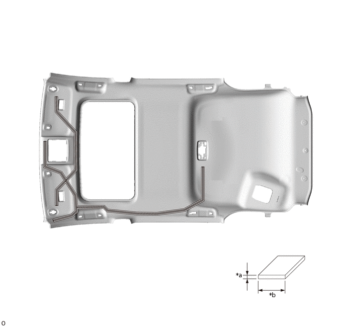
w/ Roof Headlining Support, w/ Sliding Roof:
-
Double-sided Tape
If reusing the No. 4 roof headlining support:
Apply new double-sided tape as shown in the illustration.
If replacing the No. 4 roof headlining support:
Remove the peeling paper from the No. 4 roof headlining support.
-
Double-sided Tape
If reusing the No. 2 roof headlining support:
Apply new double-sided tape as shown in the illustration.
If replacing the No. 2 roof headlining support:
Remove the peeling paper from the No. 2 roof headlining support.
Apply new double-sided tape as shown in the illustration.
*a
1 mm (0.0394 in.)
*b
15 mm (0.590 in.)
Double-sided Tape
-
-
Attach the No. 1 roof wire to the double-sided tape.
Apply new one-sided tape.
Turn the 2 connectors approximately 90° clockwise to connect them.
If any slack forms, take up the slack in the areas A shown in the illustration.
Note:Secure any wire that protrudes from the double-sided tape with one-sided tape.
*A
w/ EC Mirror
*B
w/ Lane Departure Alert System
*1
No. 1 Roof Wire
-
-
*a
90°
-
-
One-sided Tape
Double-sided Tape
Check that the No. 1 roof wire is not twisted, raised, or protruding in any way.
-
INSTALL VANITY LIGHT ASSEMBLY LH
Attach the claw to install the vanity light assembly LH.
Attach the 2 claws to connect the bulb holder to the vanity light assembly LH.
INSTALL VANITY LIGHT ASSEMBLY RH
Tip:Use the same procedure described for the LH side.
INSTALL NO. 2 ROOF HEADLINING PAD (w/o Roof Headlining Support, for Cold Area)
Remove the peeling paper from a new No. 2 roof headlining pad.
-
Silencer Marking
Align the No. 2 roof headlining pad end with the silencer markings on the roof headlining and install the No. 2 roof headlining pad end as shown in the illustration.
INSTALL NO. 2 ROOF HEADLINING PAD (w/ Roof Headlining Support)
Remove the peeling paper from a new No. 2 roof headlining pad.
-
Silencer Marking
Align the No. 2 roof headlining pad end with the silencer markings on the roof headlining and install the No. 2 roof headlining pad end as shown in the illustration.
INSTALL ROOF HEADLINING PAD (w/o Roof Headlining Support, for Cold Area)
Tip:Use the same procedure for both roof headlining pads.
Remove the peeling paper from a new roof headlining pad.
-
Silencer Marking
Align the roof headlining pad with the silencer markings on the roof headlining and install the roof headlining pad as shown in the illustration.
INSTALL ROOF HEADLINING PAD (w/ Roof Headlining Support)
Tip:Use the same procedure for both roof headlining pads.
Remove the peeling paper from a new roof headlining pad.
-
Silencer Marking
Align the roof headlining pad with the silencer markings on the roof headlining and install the roof headlining pad as shown in the illustration.
INSTALL NO. 3 ROOF SILENCER PAD
Remove the peeling paper from a new No. 3 roof silencer pad.
-
Silencer Marking
Align the No. 3 roof silencer pad with the silencer markings on the roof headlining and install the No. 3 roof silencer pad as shown in the illustration.
INSTALL NO. 1 ROOF SILENCER PAD (w/o Sliding Roof)
Remove the peeling paper from 5 new No. 1 roof silencer pads.
Align the No. 1 roof silencer pads with the silencer markings on the roof headlining and install the 5 No. 1 roof silencer pads as shown in the illustration.
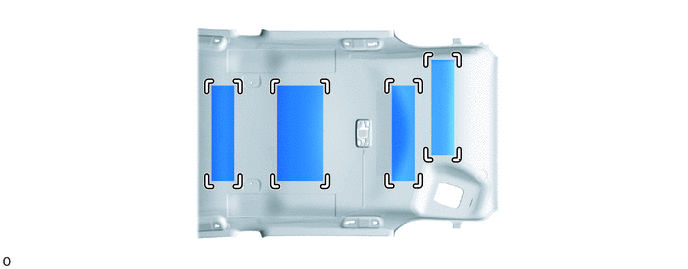
Silencer Marking
-
-
INSTALL NO. 1 ROOF SILENCER PAD (w/ Sliding Roof)
Remove the peeling paper from 2 new No. 1 roof silencer pads.
-
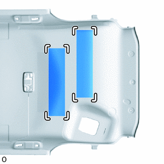
Silencer Marking
Align the No. 1 roof silencer pads with the silencer markings on the roof headlining and install the 2 No. 1 roof silencer pads as shown in the illustration.
INSTALL ROOF HEADLINING PAD RH (w/ Roof Headlining Support)
Remove the peeling paper from a new roof headlining pad RH.
-
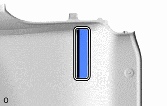
Silencer Marking
Align the roof headlining pad RH end with the silencer markings on the roof headlining and install the roof headlining pad RH end as shown in the illustration.
INSTALL CENTER ROOF HEADLINING PAD
Remove the 2 peeling papers from 2 new center roof headlining pads.
-
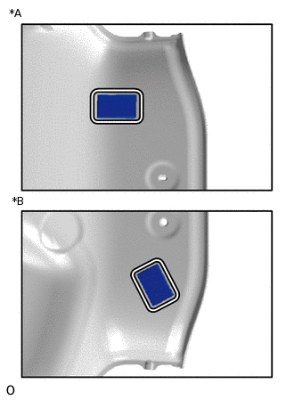
*A
for RH Side
*B
for LH Side
Silencer Marking
Align the 2 center roof headlining pads end with the silencer markings on the roof headlining and install the 2 center roof headlining pads end as shown in the illustration.