LIN COMMUNICATION SYSTEM, Diagnostic DTC:B1273
| DTC Code | DTC Name |
|---|---|
| B1273 | Sliding Roof ECU Communication Stop |
DESCRIPTION
This DTC is stored when LIN communication between the sliding roof drive gear sub-assembly and main body ECU (multiplex network body ECU) stops for 10 seconds or more.
DTC No. |
Detection Item |
DTC Detection Condition |
Trouble Area |
|---|---|---|---|
B1273 |
Sliding Roof ECU Communication Stop |
No communication between the sliding roof drive gear sub-assembly and main body ECU (multiplex network body ECU) for 10 seconds or more. |
|
WIRING DIAGRAM
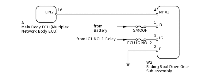
CAUTION / NOTICE / HINT
When using the intelligent tester with the engine switch off to troubleshoot:
Connect the intelligent tester to the vehicle and turn a courtesy light switch on and off at 1.5 second intervals until communication between the intelligent tester and vehicle begins.
Inspect the fuses for circuits related to this system before performing the following inspection procedure.
When the sliding roof drive gear sub-assembly is removed and reinstalled or replaced, the sliding roof drive gear sub-assembly must be initialized (Click here).
When DTC B1273 and B2325 are output simultaneously, perform troubleshooting for DTC B2325 first (Click here).
PROCEDURE
CLEAR DTC
Clear the DTCs
Body Electrical > Main Body > Clear DTCs
Result
Result
NEXT
CHECK FOR DTC
Check for DTCs
Body Electrical > Main Body > Trouble Codes
OK
DTC B1273 is not output.
Result
Result
OK
NG
CHECK HARNESS AND CONNECTOR (MAIN BODY ECU - SLIDING ROOF DRIVE GEAR)
Remove the main body ECU (multiplex network body ECU) from the driver side junction block assembly
Disconnect the W2 sliding roof drive gear sub-assembly connector.
Measure the resistance according to the value(s) in the table below.
Standard Resistance
Tester Connection
Condition
Specified Condition
A-16 (LIN2) - W2-4 (MPX1)
Always
Below 1 Ω
A-16 (LIN2) or W2-4 (MPX1) - Body ground
Always
10 kΩ or higher
Result
Result
OK
NG
NG REPAIR OR REPLACE HARNESS OR CONNECTOR
CHECK HARNESS AND CONNECTOR (SLIDING ROOF DRIVE GEAR - BATTERY AND BODY GROUND)
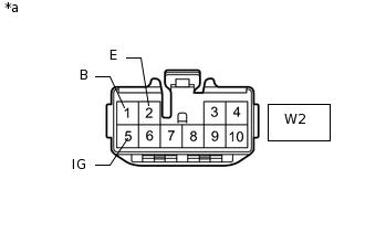
*a
Front view of wire harness connector (to Sliding Roof Drive Gear Sub-assembly)
Disconnect the W2 sliding roof drive gear sub-assembly connector.
Measure the resistance according to the value(s) in the table below.
Standard Resistance
Tester Connection
Condition
Specified Condition
W2-2 (E) - Body ground
Always
Below 1 Ω
Measure the voltage according to the value(s) in the table below.
Standard Voltage
Tester Connection
Condition
Specified Condition
W2-1 (B) - Body ground
Always
11 to 14 V
W2-5 (IG) - Body ground
Engine switch on (IG)Always
11 to 14 V
Result
Result
OK
NG
NG REPAIR OR REPLACE HARNESS OR CONNECTOR
REPLACE SLIDING ROOF DRIVE GEAR SUB-ASSEMBLY
Temporarily replace the sliding roof drive gear sub-assembly with a new or normally functioning one
Result
Result
NEXT
CLEAR DTC
Clear the DTCs
Body Electrical > Main Body > Clear DTCs
Result
Result
NEXT
CHECK FOR DTC
Check for DTCs
Body Electrical > Main Body > Trouble Codes
OK
DTC B1273 is not output.
Result
Result
OK
NG
OK END (SLIDING ROOF DRIVE GEAR IS DEFECTIVE)