TRANSMISSION CONTROL CABLE INSTALLATION
PROCEDURE
INSTALL TRANSMISSION CONTROL CABLE ASSEMBLY
Pass the transmission control cable assembly into the vehicle and install the transmission control cable assembly to the body using the 2 nuts.
5.0 N*m
51 kgf*cm
44 in.*lbf
Install the transmission control cable assembly to the rear engine mounting insulator with the bolt.
5.0 N*m
51 kgf*cm
44 in.*lbf
Install the transmission control cable assembly to the No. 1 transmission control cable bracket with a new clip.
-
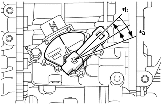
*a
P Position
*b
N Position
Turn the lever clockwise until it stops, then turn it counterclockwise 2 notches.
Install the transmission control cable assembly onto the control shaft lever with the nut.
12 N*m
122 kgf*cm
9 ft.*lbf
Turn the nut of the transmission control cable assembly 180° counterclockwise. While holding the nut in place, push in the stopper until it clicks twice.
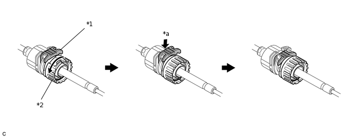
*1
Stopper
*2
Nut
*a
Push in
-
-
Install the outer part of the transmission control cable assembly to the shift lever assembly. Check that the spring is positioned at "A" and push in the stopper.
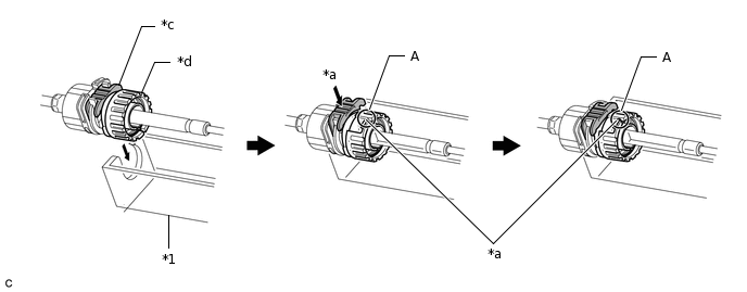
*1
Shift Lever Assembly
*2
Stopper
*3
Spring
*4
Nut
*a
Push in
-
-
Note:If the stopper cannot be pushed in, slightly turn the nut clockwise and then push in the stopper again.
Make sure that the transmission control cable assembly is securely locked.
-
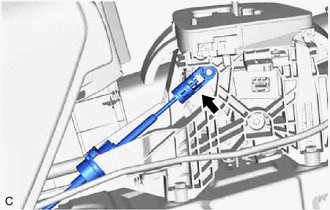
Install the end of the transmission control cable assembly to the shift lever assembly.
Note:Install the end of the transmission control cable assembly all the way to the base of the pin.
Install the end of the transmission control cable assembly so that its adjustment lock section is on the driver side.
ADJUST SHIFT LEVER POSITION
INSTALL FRONT NO. 1 FLOOR HEAT INSULATOR
Install the front No. 1 floor heat insulator to the body with the 3 nuts.
5.5 N*m
56 kgf*cm
49 in.*lbf
INSTALL FRONT EXHAUST PIPE ASSEMBLY (TWC: Front and Rear Catalyst) (for 1ZR-FAE)
INSTALL FRONT EXHAUST PIPE ASSEMBLY (TWC: Front and Rear Catalyst) (for 1ZR-FE)
INSTALL FRONT EXHAUST PIPE ASSEMBLY (TWC: Front and Rear Catalyst) (for 2ZR-FE)
INSTALL FRONT CENTER FLOOR BRACE SUB-ASSEMBLY (for 1ZR-FAE)
INSTALL FRONT CENTER FLOOR BRACE (for 1ZR-FE)
INSTALL FRONT CENTER FLOOR BRACE (for 2ZR-FE)
INSTALL BATTERY CARRIER ASSEMBLY (for 1ZR-FAE)
INSTALL BATTERY CARRIER ASSEMBLY (for 1ZR-FE)
INSTALL BATTERY CARRIER ASSEMBLY (for 2ZR-FE)
INSTALL BATTERY (for 1ZR-FAE)
INSTALL BATTERY (for 1ZR-FE)
INSTALL BATTERY (for 2ZR-FE)
INSTALL AIR CLEANER CASE SUB-ASSEMBLY (for 1ZR-FAE)
INSTALL AIR CLEANER CASE SUB-ASSEMBLY (for 1ZR-FE)
INSTALL AIR CLEANER CASE SUB-ASSEMBLY (for 2ZR-FE)
INSTALL AIR CLEANER CAP SUB-ASSEMBLY (for 1ZR-FAE)
INSTALL AIR CLEANER CAP SUB-ASSEMBLY (for 1ZR-FE)
INSTALL AIR CLEANER CAP SUB-ASSEMBLY (for 2ZR-FE)
INSTALL NO. 2 CYLINDER HEAD COVER (for 1ZR-FAE)
INSTALL NO. 2 CYLINDER HEAD COVER (for 1ZR-FE)
INSTALL NO. 2 CYLINDER HEAD COVER (for 2ZR-FE)
INSTALL REAR CONSOLE BOX ASSEMBLY (for Hatchback, Wagon)
INSTALL REAR CONSOLE BOX ASSEMBLY (for Sedan)
INSPECT SHIFT LEVER POSITION
INSPECT FOR EXHAUST GAS LEAK