INTAKE MANIFOLD INSTALLATION
CAUTION / NOTICE / HINT
Note
-
When replacing the parts in the following chart (A), replace the No. 1 injection pipe sub-assembly, No. 2 injection pipe sub-assembly, No. 3 injection pipe sub-assembly, No. 4 injection pipe sub-assembly and/or fuel inlet pipe sub-assembly with new ones.
Replaced Parts (A) Pipes Requiring New Replacement
-
Injector assembly (including shuffling the injector assemblies between the cylinders)
-
Common rail assembly
-
Cylinder head sub-assembly
-
No. 1 injection pipe sub-assembly
-
No. 2 injection pipe sub-assembly
-
No. 3 injection pipe sub-assembly
-
No. 4 injection pipe sub-assembly
-
Supply pump assembly
-
Common rail assembly
-
Cylinder block sub-assembly
-
Cylinder head sub-assembly
-
Cylinder head gasket
-
Timing Gear Case Assembly
Fuel inlet pipe sub-assembly -
-
After removing the No. 1 injection pipe sub-assembly, No. 2 injection pipe sub-assembly, No. 3 injection pipe sub-assembly, No. 4 injection pipe sub-assembly and fuel inlet pipe sub-assembly, clean them with a brush and compressed air.
PROCEDURE
-
INSTALL INTAKE MANIFOLD
-
Install a new gasket to the cylinder head sub-assembly.
-
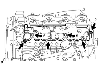
Temporarily install the intake manifold with the 4 bolts 2 nuts.
-
Tighten the 4 bolts and 2 nuts in the order shown in the illustration.
- Torque:
- 29 N*m { 296 kgf*cm, 21 ft.*lbf }
-
-
INSTALL NO. 2 NOZZLE LEAKAGE PIPE ASSEMBLY
-
INSTALL NO. 4 INJECTION PIPE SUB-ASSEMBLY
-
INSTALL NO. 1, NO. 2 AND NO. 3 INJECTION PIPE SUB-ASSEMBLY
-
INSTALL INTAKE AIR CONNECTOR
-
Install a new gasket and the intake air connector to the intake manifold with the 2 nuts and bolt.
- Torque:
- 20 N*m { 204 kgf*cm, 15 ft.*lbf }
-
-
INSTALL NO. 2 INTAKE AIR CONNECTOR BRACKET
-
Install the No. 2 intake air connector bracket to the cylinder head sub-assembly and intake manifold with the 3 bolts.
- Torque:
- 20 N*m { 204 kgf*cm, 15 ft.*lbf }
-
-
INSTALL VACUUM SWITCHING VALVE BRACKET
-
Install the vacuum switching valve bracket with the 2 bolts.
- Torque:
- 20 N*m { 204 kgf*cm, 15 ft.*lbf }
-
-
INSTALL ENGINE OIL LEVEL DIPSTICK GUIDE
-
Apply a small amount of clean engine oil to the O-ring.
-
Install a new O-ring to the engine oil level dipstick guide.
-
Install the engine oil level dipstick guide with the bolt.
- Torque:
- 8.0 N*m { 82 kgf*cm, 71 in.*lbf }
-
Install the injection pipe clamp with the bolt.
- Torque:
- 5.0 N*m { 51 kgf*cm, 44 in.*lbf }
-
Install the engine oil level dipstick.
-
-
INSTALL MANIFOLD STAY
-
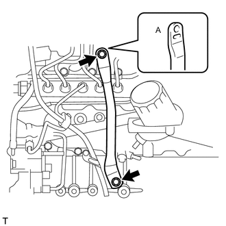
Install the manifold stay to the intake manifold and cylinder block sub-assembly with the 2 bolts.
- Torque:
- 19 N*m { 194 kgf*cm, 14 ft.*lbf }
Tech Tips
The manifold stay indented area (labeled A) must face the intake manifold.
-
-
INSTALL DIESEL THROTTLE BODY ASSEMBLY
-
CONNECT CABLE TO NEGATIVE BATTERY TERMINAL
Note
When disconnecting the cable, some systems need to be initialized after the cable is reconnected.
-
BLEED AIR FROM FUEL SYSTEM
-
INSPECT FOR FUEL LEAK
-
INSPECT FOR OIL LEAK
-
INSPECT ENGINE OIL LEVEL