STEERING GEAR REASSEMBLY

CAUTION / NOTICE / HINT
Note
-
When using a vise, place aluminum plates between the part and vise.
-
When using a vise, do not overtighten it.
Tech Tips
-
Use the same procedure for RHD and LHD vehicles.
-
The procedure listed below is for LHD vehicles.
PROCEDURE
-
INSTALL STEERING RACK END SUB-ASSEMBLY
-
Temporarily install the 2 steering rack end sub-assembly to the steering rack.
-
Fill up the ball joints of the steering rack end sub-assembly with MP grease.
-
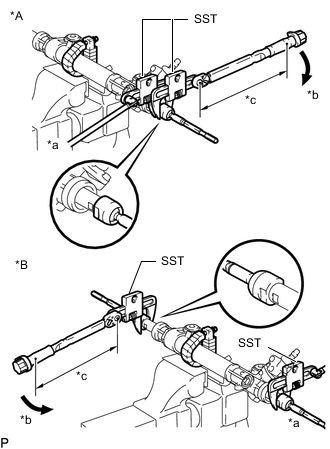
*A for LH Side *B for RH Side *a Hold *b Turn *c Torque Wrench Fulcrum Length Using SST, install the steering rack end sub-assembly (LH side) to the steering rack.
- SST
- 09922-10010
- Torque:
- Specified tightening torque:
- 103 N*m { 1050 kgf*cm, 76 ft.*lbf }
Note
Rotate SST in the direction shown in the illustration.
Tech Tips
-
Calculate the torque wrench reading when changing the fulcrum length of the torque wrench.
-
When using SST (fulcrum length of 128.5 mm(5.059 in.)) + torque wrench (fulcrum length of 400 mm (15.748 in.)): 78 N*m (795 kgf*cm, 58ft.*lbf)
-
-
INSTALL STEERING RACK BOOT LH
-
Install the steering rack boot LH.
Note
-
Make sure that the steering rack boot LH is free of rust and foreign matter.
-
Be careful not to damage or twist the steering rack boot.
-
-
-
INSTALL STEERING RACK BOOT RH
Tech Tips
Use the same procedure described for the LH side.
-
INSTALL STEERING RACK BOOT CLAMP LH
-
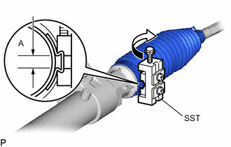
Using SST, install a new steering rack boot clamp LH as shown in the illustration.
- SST
- 09240-00020
- 09521-24010
Standard clearance (A) 3.0 mm (0.118 in.) or less Note
Be careful not to damage the steering rack boot.
-
-
INSTALL STEERING RACK BOOT CLAMP RH
Tech Tips
Use the same procedure described for the LH side.
-
INSTALL STEERING RACK BOOT CLIP LH
-
Using pliers, install the steering rack boot clip LH.
-
-
INSTALL STEERING RACK BOOT CLIP RH
Tech Tips
Use the same procedure described for the LH side.
-
INSPECT POWER STEERING LINK ASSEMBLY
-
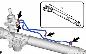
INSTALL STEERING TURN PRESSURE TUBE (for 2WD)
-
Apply power steering fluid to 4 new O-rings, and install the O-rings to the steering turn pressure tubes.
-
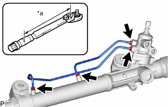
*a Torque Wrench Fulcrum Length Using a union nut wrench, install the 2 steering turn pressure tubes.
- Torque:
- 12.5 N*m { 127 kgf*cm, 9 ft.*lbf }
Note
Do not damage the O-rings.
Tech Tips
-
Calculate the torque wrench reading when changing the fulcrum length of the torque wrench.
-
When using a union nut wrench (fulcrum length of 20 mm (0.7874 in.)) + torque wrench (fulcrum length of 162 mm (6.3779 in.)): 11.1 N*m (113 kgf*cm, 8 ft.*lbf)
-
-
INSTALL STEERING TURN PRESSURE TUBE (for 4WD and Pre-Runner)
-
Apply power steering fluid to 3 new O-rings, and install the O-rings to the steering turn pressure tubes.
-
for LHD:
-
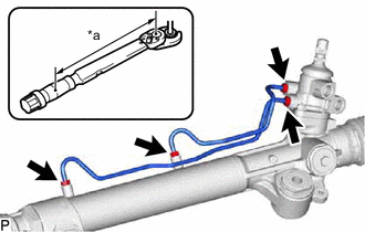
Using a union nut wrench, install the 2 steering turn pressure tubes.
- Torque:
- 12.5 N*m { 127 kgf*cm, 9 ft.*lbf }
Note
Do not damage the O-rings.
Tech Tips
-
Calculate the torque wrench reading when changing the fulcrum length of the torque wrench.
-
When using a union nut wrench (fulcrum length of 20 mm (0.7874 in.)) + torque wrench (fulcrum length of 162 mm (6.3779 in.)): 11.1 N*m (113 kgf*cm, 8 ft.*lbf)
-
-
*a Torque Wrench Fulcrum Length for RHD:
-
Using a union nut wrench, install the 2 steering turn pressure tubes.
- Torque:
- 12.5 N*m { 127 kgf*cm, 9 ft.*lbf }
Note
Do not damage the O-rings.
Tech Tips
-
Calculate the torque wrench reading when changing the fulcrum length of the torque wrench.
-
When using a union nut wrench (fulcrum length of 20 mm (0.7874 in.)) + torque wrench (fulcrum length of 162 mm (6.3779 in.)): 11.1 N*m (113 kgf*cm, 8 ft.*lbf)
-
Install the 2 new gaskets and union bolt.
- Torque:
- 29.4 N*m { 300 kgf*cm, 22 ft.*lbf }
-
-
-
INSTALL TIE ROD END SUB-ASSEMBLY LH
-
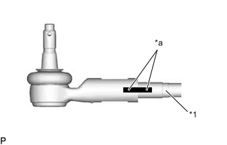
*1 Rack End *a Matchmark Screw the lock nut and tie rod end sub-assembly LH onto the rack end until the matchmarks are aligned.
-
After adjusting the toe-in, tighten the lock nut.
-
-
INSTALL TIE ROD END SUB-ASSEMBLY RH
Tech Tips
Use the same procedure described for the LH side.