AIR CONDITIONING SYSTEM(for Manual Air Conditioning System) Air Conditioning Compressor Magnetic Clutch Circuit
DESCRIPTION
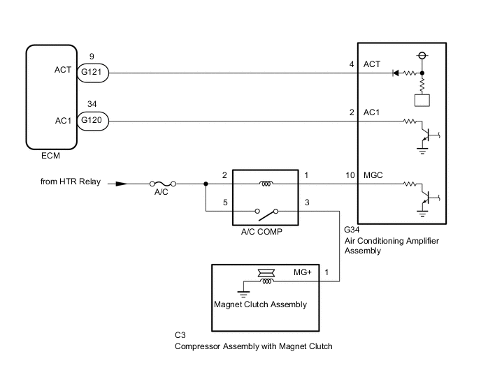
The air conditioning amplifier assembly outputs the magnet clutch on request signal to the ECM. The ECM sends a magnet clutch on permission signal to the air conditioning amplifier assembly. The air conditioning amplifier assembly turns the magnet clutch on based on this signal.
WIRING DIAGRAM
Figure 1. w/ PTC Heater:
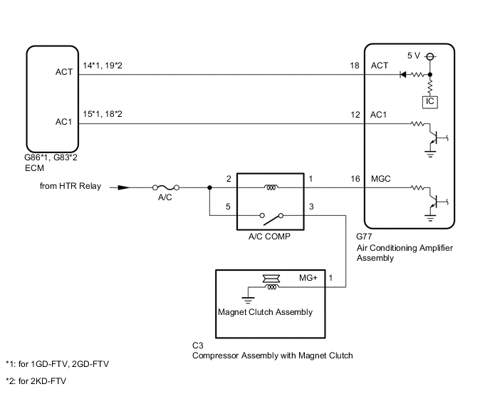
Figure 2. w/o PTC Heater (except 5L-E):
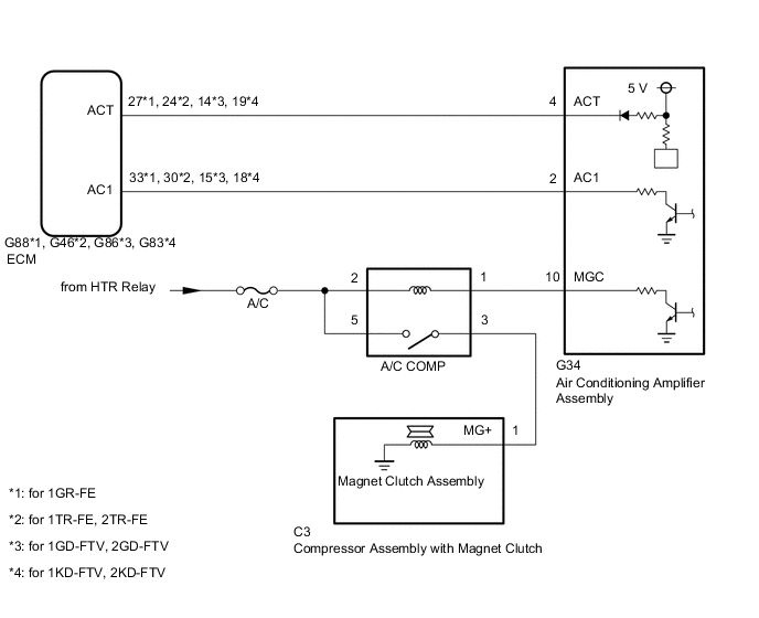
Figure 3. w/o PTC Heater (for 5L-E):
CAUTION / NOTICE / HINT
Note
Inspect the fuses and relays for circuits related to this system before performing the following procedure.
PROCEDURE
-
READ VALUE USING GTS (A/C SIGNAL)
-
Connect the GTS to the DLC3.
-
Turn the ignition switch to ON.
-
Turn the GTS on.
-
Enter the following menus: Body Electrical / Engine and ECT / Data List.
-
Check the value(s) by referring to the table below.
Powertrain > Engine and ECT > Data ListTester Display Measurement Item Range Normal Condition Diagnostic Note A/C Signal Magnet clutch on request signal ON or OFF ON: "A/C" switch on
OFF: "A/C" switch off
Operates with the engine idling and the blower switch on (LO level).
Powertrain > Engine and ECT > Data ListTester Display A/C Signal OK The display is as specified in normal condition. Result Proceed to OK NG
NG 
CHECK HARNESS AND CONNECTOR (AIR CONDITIONING AMPLIFIER ASSEMBLY - ECM) Click here
OK 
-
-
INSPECT MAGNET CLUTCH RELAY (A/C COMP)
-
Remove the A/C COMP relay from the No. 4 instrument panel relay block assembly.
-
Inspect the A/C COMP relay.
Result Proceed to OK NG
NG 
REPLACE MAGNET CLUTCH RELAY (A/C COMP RELAY)
OK
-
-
CHECK HARNESS AND CONNECTOR (AIR CONDITIONING AMPLIFIER - BATTERY)
-
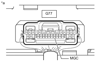
w/ PTC Heater:
-
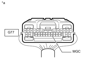
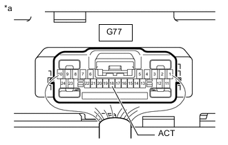
*a Rear view of wire harness connector
(to Air Conditioning Amplifier Assembly)
Disconnect the air conditioning amplifier assembly connector.
-
Measure the voltage according to the value(s) in the table below.
Standard Voltage Tester Connection Switch Condition Specified Condition G77-16 (MGC) - Body ground Ignition switch off Below 1 V G77-16 (MGC) - Body ground Ignition switch ON 11 to 14 V
-
-
w/o PTC Heater:
-
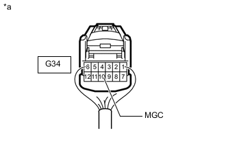
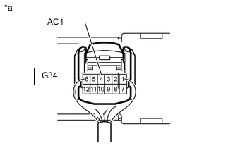
*a Rear view of wire harness connector
(to Air Conditioning Amplifier Assembly)
Disconnect the air conditioning amplifier assembly connector.
-
Measure the voltage according to the value(s) in the table below.
Standard Voltage Tester Connection Switch Condition Specified Condition G34-10 (MGC) - Body ground Ignition switch off Below 1 V G34-10 (MGC) - Body ground Ignition switch ON 11 to 14 V
Result Proceed to OK NG -
NG
REPAIR OR REPLACE HARNESS OR CONNECTOR
OK
-
-
CHECK AIR CONDITIONING AMPLIFIER ASSEMBLY
-
Remove the air conditioning amplifier assembly with its connectors still connected.
-
*a Component with harness connected
(Air Conditioning Amplifier Assembly)
w/ PTC Heater:
-
Measure the voltage according to the value(s) in the table below.
Standard Voltage Tester Connection Condition Specified Condition G77-16 (MGC) - Body ground
-
Engine idling
-
Blower switch: LO or higher
-
"A/C" switch: On (magnet clutch on)
Below 1 V G77-16 (MGC) - Body ground
-
Engine idling
-
Blower switch: LO or higher
-
"A/C" switch: Off or on (magnet clutch off)
11 to 14 V -
-
-

*a Component with harness connected
(Air Conditioning Amplifier Assembly)
w/o PTC Heater:
-
Measure the voltage according to the value(s) in the table below.
Standard Voltage Tester Connection Condition Specified Condition G34-10 (MGC) - Body ground
-
Engine idling
-
Blower switch: LO or higher
-
"A/C" switch: On (magnet clutch on)
Below 1 V G34-10 (MGC) - Body ground
-
Engine idling
-
Blower switch: LO or higher
-
"A/C" switch: Off or on (magnet clutch off)
11 to 14 V -
Result Proceed to OK NG -
NG
CHECK HARNESS AND CONNECTOR (AIR CONDITIONING AMPLIFIER ASSEMBLY - ECM) Click here
OK
-
-
INSPECT MAGNET CLUTCH ASSEMBLY
-
Remove the compressor assembly with magnet clutch.
-
for 1GR-FE: Click here
-
for 2TR-FE: Click here
-
for 1GD-FTV, 2GD-FTV: Click here
-
for 1KD-FTV, 2KD-FTV: Click here
-
for 5L-E: Click here
-
-
Inspect the compressor assembly with magnet clutch.
-
for 1GR-FE: Click here
-
for 2TR-FE: Click here
-
for 1GD-FTV, 2GD-FTV: Click here
-
for 1KD-FTV, 2KD-FTV: Click here
-
for 5L-E: Click here
Result Proceed to OK NG -
NG
REPLACE MAGNET CLUTCH ASSEMBLY for 1GR-FE: Click here for 2TR-FE: Click here for 1GD-FTV, 2GD-FTV: Click here for 1KD-FTV, 2KD-FTV: Click here for 5L-E: Click here
OK
-
-
CHECK HARNESS AND CONNECTOR (A/C COMP RELAY - COMPRESSOR ASSEMBLY WITH MAGNET CLUTCH AND BATTERY)
-
Remove the A/C COMP relay from the No. 4 instrument panel junction block assembly.
-
Disconnect the C3 compressor assembly with magnet clutch connector.
-
Measure the resistance according to the value(s) in the table below.
Standard Resistance Tester Connection Condition Specified Condition Relay terminal 3 - C3-1 (MG+) Always Below 1 Ω Relay terminal 3 or C3-1 (MG+) - Body ground Always 10 kΩ or higher -
Measure the voltage according to the value(s) in the table below.
Standard Voltage Tester Connection Switch Condition Specified Condition Relay terminal 5 - Body ground Ignition switch off Below 1 V Relay terminal 5 - Body ground Ignition switch ON 11 to 14 V Result Proceed to OK NG
OK
PROCEED TO NEXT SUSPECTED AREA SHOWN IN PROBLEM SYMPTOMS TABLE Click here
NG
REPAIR OR REPLACE HARNESS OR CONNECTOR
-
-
CHECK HARNESS AND CONNECTOR (AIR CONDITIONING AMPLIFIER ASSEMBLY - ECM)
-
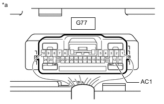
w/ PTC Heater:
-
Disconnect the G77 air conditioning amplifier assembly connector.
-
Disconnect the G86*1 or G83*2 ECM connector.
-
*1: for 1GD-FTV, 2GD-FTV
-
*2: for 2KD-FTV
-
-
Measure the resistance according to the value(s) in the table below.
Standard Resistance for 1GD-FTV, 2GD-FTV Tester Connection Condition Specified Condition G77-12 (AC1) - G86-15 (AC1) Always Below 1 Ω G77-18 (ACT) - G86-14 (ACT) Always Below 1 Ω G77-12 (AC1) or G86-15 (AC1) - Body ground Always 10 kΩ or higher G77-18 (ACT) or G86-14 (ACT) - Body ground Always 10 kΩ or higher for 2KD-FTV Tester Connection Condition Specified Condition G77-12 (AC1) - G83-19 (AC1) Always Below 1 Ω G77-18 (ACT) - G83-18 (ACT) Always Below 1 Ω G77-12 (AC1) or G83-19 (AC1) - Body ground Always 10 kΩ or higher G77-18 (ACT) or G83-18 (ACT) - Body ground Always 10 kΩ or higher
-
-
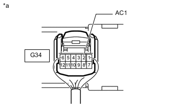
w/o PTC Heater:
-
Disconnect the G34 air conditioning amplifier assembly connector.
-
except 5L-E:
-
Disconnect the G88*1, G46*2, G86*3 or G83*4 ECM connector.
-
*1: for 1GR-FE
-
*2: for 2TR-FE
-
*3: for 1GD-FTV, 2GD-FTV
-
*4: for 1KD-FTV, 2KD-FTV
-
-
for 5L-E:
-
Disconnect the G120 and G121ECM connectors.
-
-
Measure the resistance according to the value(s) in the table below.
Standard Resistance for 1GR-FE Tester Connection Condition Specified Condition G34-2 (AC1) - G88-33 (AC1) Always Below 1 Ω G34-4 (ACT) - G88-27 (ACT) Always Below 1 Ω G34-2 (AC1) or G88-33 (AC1) - Body ground Always 10 kΩ or higher G34-4 (ACT) or G88-27 (ACT) - Body ground Always 10 kΩ or higher for 2TR-FE Tester Connection Condition Specified Condition G34-2 (AC1) - G46-30 (AC1) Always Below 1 Ω G34-4 (ACT) - G46-24 (ACT) Always Below 1 Ω G34-2 (AC1) or G46-30 (AC1) - Body ground Always 10 kΩ or higher G34-4 (ACT) or G46-24 (ACT) - Body ground Always 10 kΩ or higher for 1GD-FTV, 2GD-FTV Tester Connection Condition Specified Condition G34-2 (AC1) - G86-15 (AC1) Always Below 1 Ω G34-4 (ACT) - G86-14 (ACT) Always Below 1 Ω G34-2 (AC1) or G86-15 (AC1) - Body ground Always 10 kΩ or higher G34-4 (ACT) or G86-14 (ACT) - Body ground Always 10 kΩ or higher for 1KD-FTV, 2KD-FTV Tester Connection Condition Specified Condition G34-2 (AC1) - G83-18 (AC1) Always Below 1 Ω G34-4 (ACT) - G83-19 (ACT) Always Below 1 Ω G34-2 (AC1) or G83-18 (AC1) - Body ground Always 10 kΩ or higher G34-4 (ACT) or G83-19 (ACT) - Body ground Always 10 kΩ or higher for 5L-E Tester Connection Condition Specified Condition G34-2 (AC1) - G120-34 (AC1) Always Below 1 Ω G34-4 (ACT) - G121-9 (ACT) Always Below 1 Ω G34-2 (AC1) or G120-34 (AC1) - Body ground Always 10 kΩ or higher G34-4 (ACT) or G121-9 (ACT) - Body ground Always 10 kΩ or higher
Result Proceed to OK NG -
NG
REPAIR OR REPLACE HARNESS OR CONNECTOR
OK
-
-
CHECK AIR CONDITIONING AMPLIFIER ASSEMBLY
-
Remove the air conditioning amplifier assembly with its connectors still connected.
-
*a Component with harness connected
(Air Conditioning Amplifier Assembly)
w/ PTC Heater:
-
Measure the voltage according to the value(s) in the table below.
Standard Voltage Tester Connection Condition Specified Condition G77-12 (AC1) - Body ground
-
Engine idling
-
Blower switch: LO or higher
-
"A/C" switch: On
Below 1 V G77-12 (AC1) - Body ground
-
Engine idling
-
Blower switch on (LO level)
-
"A/C" switch: Off
11 to 14 V -
-
-
*a Component with harness connected
(Air Conditioning Amplifier Assembly)
w/o PTC Heater:
-
Measure the voltage according to the value(s) in the table below.
Standard Voltage Tester Connection Condition Specified Condition G34-2 (AC1) - Body ground
-
Engine idling
-
Blower switch: LO or higher
-
"A/C" switch: On
Below 1 V G34-2 (AC1) - Body ground
-
Engine idling
-
Blower switch on (LO level)
-
"A/C" switch: Off
11 to 14 V -
Result Proceed to OK NG -
OK
REPLACE ECM for 1GR-FE: Click here for 2TR-FE: Click here for 1GD-FTV: Click here for 2GD-FTV: Click here for 1KD-FTV: Click here for 2KD-FTV: Click here for 5L-E: Click here
NG
REPLACE AIR CONDITIONING AMPLIFIER ASSEMBLY Click here
-
-
CHECK HARNESS AND CONNECTOR (AIR CONDITIONING AMPLIFIER ASSEMBLY - ECM)
-
w/ PTC Heater:
-
Disconnect the G77 air conditioning amplifier assembly connector.
-
Disconnect the G86*1 or G83*2 ECM connector.
-
*1: for 1GD-FTV, 2GD-FTV
-
*2: for 2KD-FTV
-
-
Measure the resistance according to the value(s) in the table below.
Standard Resistance for 1GD-FTV, 2GD-FTV Tester Connection Condition Specified Condition G77-18 (ACT) - G86-14 (ACT) Always Below 1 Ω G77-18 (ACT) or G86-14 (ACT) - Body ground Always 10 kΩ or higher for 2KD-FTV Tester Connection Condition Specified Condition G77-18 (ACT) - G83-19 (ACT) Always Below 1 Ω G77-18 (ACT) or G83-19 (ACT) - Body ground Always 10 kΩ or higher
-
-
w/o PTC Heater:
-
Disconnect the G34 air conditioning amplifier assembly connector.
-
Disconnect the G88*1, G46*2, G86*3, G83*4 or G121*5 ECM connector.
-
*1: for 1GR-FE
-
*2: for 2TR-FE
-
*3: for 1GD-FTV, 2GD-FTV
-
*4: for 1KD-FTV, 2KD-FTV
-
*5: for 5L-E
-
-
Measure the resistance according to the value(s) in the table below.
Standard Resistance for 1GR-FE Tester Connection Condition Specified Condition G34-4 (ACT) - G88-27 (ACT) Always Below 1 Ω G34-4 (ACT) or G88-27 (ACT) - Body ground Always 10 kΩ or higher for 2TR-FE Tester Connection Condition Specified Condition G34-4 (ACT) - G46-24 (ACT) Always Below 1 Ω G34-4 (ACT) or G46-24 (ACT) - Body ground Always 10 kΩ or higher for 1GD-FTV, 2GD-FTV Tester Connection Condition Specified Condition G34-4 (ACT) - G86-14 (ACT) Always Below 1 Ω G34-4 (ACT) or G86-14 (ACT) - Body ground Always 10 kΩ or higher for 1KD-FTV, 2KD-FTV Tester Connection Condition Specified Condition G34-4 (ACT) - G83-19 (ACT) Always Below 1 Ω G34-4 (ACT) or G83-19 (ACT) - Body ground Always 10 kΩ or higher for 5L-E Tester Connection Condition Specified Condition G34-4 (ACT) - G121-9 (ACT) Always Below 1 Ω G34-4 (ACT) or G121-9 (ACT) - Body ground Always 10 kΩ or higher
Result Proceed to OK NG -
NG
REPAIR OR REPLACE HARNESS OR CONNECTOR
OK
-
-
CHECK ECM
-
Remove the air conditioning amplifier assembly with its connectors still connected.
-
*a Component with harness connected
(Air Conditioning Amplifier Assembly)
w/ PTC Heater:
-
Measure the voltage according to the value(s) in the table below.
Standard Voltage Tester Connection Condition Specified Condition G77-18 (ACT) - Body ground
-
Engine running
-
Blower switch: LO or higher
-
"A/C" switch: Off or on (magnet clutch off)
Below 1 V G77-18 (ACT) - Body ground
-
Engine running
-
Blower switch: LO or higher
-
"A/C" switch: On (magnet clutch on)
4.5 to 5.5 V -
-
-
*a Component with harness connected
(Air Conditioning Amplifier Assembly)
w/o PTC Heater:
-
Measure the voltage according to the value(s) in the table below.
Standard Voltage Tester Connection Condition Specified Condition G34-4 (ACT) - Body ground
-
Engine running
-
Blower switch: LO or higher
-
"A/C" switch: Off or on (magnet clutch off)
Below 1 V G34-4 (ACT) - Body ground
-
Engine running
-
Blower switch: LO or higher
-
"A/C" switch: On (magnet clutch on)
4.5 to 5.5 V -
Result Proceed to OK NG -
OK
REPLACE AIR CONDITIONING AMPLIFIER ASSEMBLY Click here
NG
REPLACE ECM for 1GR-FE: Click here for 2TR-FE: Click here for 1GD-FTV: Click here for 2GD-FTV: Click here for 1KD-FTV: Click here for 2KD-FTV: Click here for 5L-E: Click here
-