AUTOMATIC TRANSMISSION SYSTEM (for 1KD-FTV) TERMINALS OF ECU
Tech Tips
Each ECU terminal's standard voltage is shown in the table below.
In the table, first follow the information under "Condition". Look under "Symbols (Terminal No.)" for the terminals to be inspected. The standard voltage between the terminals is shown under "Specified Condition".
Use the illustration below as a reference for the ECU terminals.
-
ECM (w/ DPF)
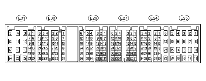
Terminal No. (Symbols) Wiring Color Terminal Description Condition Specified Condition E24-26 (NSW) - E25-1 (E1) L-Y - BR Park/neutral position switch signal Ignition switch ON and shift lever on P or N Below 3 V E24-26 (NSW) - E25-1 (E1) L-Y - BR Park/neutral position switch signal Ignition switch ON and shift lever not on P or N 11 to 14 V E31-8 (STP) - E25-1 (E1) G-W - BR Stop light switch signal Brake pedal is depressed 7.5 to 14 V E31-8 (STP) - E25-1 (E1) G-W - BR Stop light switch signal Brake pedal is released Below 1.5 V E27-13 (VC) - E25-1 (E1) R-W - BR Power source of sensor (specific voltage) Ignition switch ON 4.5 to 5.5 V E31-24 (+B) - E25-1 (E1) B - BR Power source of ECM Ignition switch ON 11 to 14 V E24-24 (CAN+) - E25-1 (E1) V - BR CAN communication line Ignition switch ON Pulse generation
(see waveform 8)
E24-18 (CAN-) - E25-1 (E1) P - BR CAN communication line Ignition switch ON Pulse generation
(see waveform 9)
-
ECM (w/o DPF)
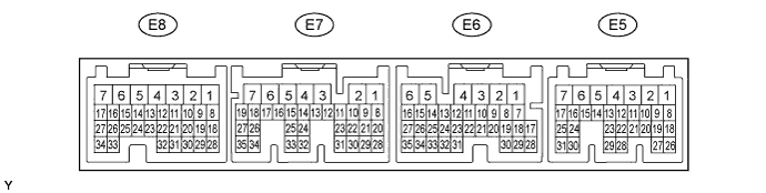
Terminal No. (Symbols) Wiring Color Terminal Description Condition Specified Condition E5-6 (NSW) - E7-7 (E1) L-Y - BR Park/neutral position switch signal Ignition switch ON and shift lever on P or N Below 3 V E5-6 (NSW) - E7-7 (E1) L-Y - BR Park/neutral position switch signal Ignition switch ON and shift lever not on P or N 11 to 14 V E6-15 (STP) - E7-7 (E1) G-W - BR Stop light switch signal Brake pedal is depressed 7.5 to 14 V E6-15 (STP) - E7-7 (E1) G-W - BR Stop light switch signal Brake pedal is released Below 1.5 V E8-18 (VC) - E7-7 (E1) R-W - BR Power source of sensor (specific voltage) Ignition switch ON 4.5 to 5.5 V E5-1 (+B) - E7-7 (E1) B - BR Power source of ECM Ignition switch ON 11 to 14 V E6-22 (CAN+) - E7-7 (E1) V - BR CAN communication line Ignition switch ON Pulse generation
(see waveform 8)
E6-21 (CAN-) - E7-7 (E1) P - BR CAN communication line Ignition switch ON Pulse generation
(see waveform 9)
-
TCM
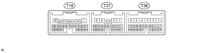
Terminal No. (Symbols) Wiring Color Terminal Description Condition Specified Condition T38-5 (BATT) - T19-1 (E1) L - BR Battery (for measuring battery voltage and for TCM memory) Always 11 to 14 V T19-12 (NSW) - T19-1 (E1) L-Y - BR Park/neutral position switch signal Ignition switch ON and shift lever on P or N Below 3 V T19-12 (NSW) - T19-1 (E1) L-Y - BR Park/neutral position switch signal Ignition switch ON and shift lever not on P or N 11 to 14 V T19-11 (STA) - T19-1 (E1) B-Y - BR Starter signal Cranking 6 V or higher T37-9 (R) - T19-1 (E1) R-Y - BR R shift position switch signal Ignition switch ON and shift lever on R 11 to 14 V T37-9 (R) - T19-1 (E1) R-Y - BR R shift position switch signal Ignition switch ON and shift lever not on R Below 1.5 V T37-8 (D) - T19-1 (E1) G-Y - BR D shift position switch signal Ignition switch ON and shift lever on D or 4 11 to 14 V T37-8 (D) - T19-1 (E1) G-Y - BR D shift position switch signal Ignition switch ON and shift lever not on D or 4 Below 1.5 V T37-13 (4) - T19-1 (E1) G-O - BR 4 shift position switch signal Ignition switch ON and shift lever on 4 11 to 14 V T37-13 (4) - T19-1 (E1) G-O - BR 4 shift position switch signal Ignition switch ON and shift lever not on 4 Below 1.5 V T37-12 (3) - T19-1 (E1) L - BR 3 shift position switch signal Ignition switch ON and shift lever on 3 11 to 14 V T37-12 (3) - T19-1 (E1) L - BR 3 shift position switch signal Ignition switch ON and shift lever not on 3 Below 1.5 V T37-11 (2) - T19-1 (E1) G-R - BR 2 shift position switch signal Ignition switch ON and shift lever on 2 11 to 14 V T37-11 (2) - T19-1 (E1) G-R - BR 2 shift position switch signal Ignition switch ON and shift lever not on 2 Below 1.5 V T37-10 (L) - T19-1 (E1) GR-L - BR L shift position switch signal Ignition switch ON and shift lever on L 11 to 14 V T37-10 (L) - T19-1 (E1) GR-L - BR L shift position switch signal Ignition switch ON and shift lever not on L Below 1.5 V T19-18 (S1) - T19-1 (E1) GR - BR S1 solenoid signal 1st or 2nd gear 11 to 14 V T19-18 (S1) - T19-1 (E1) GR - BR S1 solenoid signal 3rd, 4th or 5th gear Below 1.5 V T19-17 (S2) - T19-1 (E1) W-L - BR S2 solenoid signal 2nd or 3rd gear 11 to 14 V T19-17 (S2) - T19-1 (E1) W-L - BR S2 solenoid signal 1st, 4th or 5th gear Below 1.5 V T19-16 (SR) - T19-1 (E1) G - BR SR solenoid signal 5th gear 11 to 14 V T19-16 (SR) - T19-1 (E1) G - BR SR solenoid signal 1st gear Below 1.5 V T19-9 (SL1+) - T19-8 (SL1-) GR - V SL1 solenoid signal Engine is idling Pulse generation
(see waveform 1)
T19-7 (SL2+) - T19-6 (SL2-) W - R-W SL2 solenoid signal Engine is idling Pulse generation
(see waveform 2)
T19-20 (SLT+) - T19-19 (SLT-) G-Y - L-B SLT solenoid signal Engine is idling Pulse generation
(see waveform 3)
T19-22 (SLU+) - T19-21 (SLU-) B - Y SLUT solenoid signal 4th (lock-up) or 5th (lock-up) gear Pulse generation
(see waveform 4)
T19-25 (THO1) - T19-23 (E2) L - G No. 1 ATF temperature sensor signal ATF temperature: 115°C (239°F) or more Below 1.5 V T19-24 (THO2) - T19-23 (E2) BR - G No. 2 ATF temperature sensor signal ATF temperature: 115°C (239°F) or more Below 1.5 V T38-14 (STP) - T19-1 (E1) G-W - BR Stop light switch signal Brake pedal is depressed 7.5 to 14 V T38-14 (STP) - T19-1 (E1) G-W - BR Stop light switch signal Brake pedal is released Below 1.5 V T19-3 (NT+) - T19-2 (NT-) V - P Speed sensor (NT) signal Engine is idling Pulse generation
(see waveform 5)
T19-30 (SP2+) - T19-29 (SP2-) R - G Speed sensor (SP2) signal Vehicle speed 20 km/h (12 mph) Pulse generation
(see waveform 6)
T37-15 (L4) - T19-1 (E1) G-W - BR L4 shift position switch signal Ignition switch ON and transfer shift lever on L4 11 to 14 V T37-15 (L4) - T19-1 (E1) G-W - BR L4 shift position switch signal Ignition switch ON and transfer shift lever not on L4 Below 1.5 V T37-16 (TFN) - T19-1 (E1) W-G - BR N shift position switch signal Ignition switch ON and transfer shift lever on N 11 to 14 V T37-16 (TFN) - T19-1 (E1) W-G - BR N shift position switch signal Ignition switch ON and transfer shift lever not on N Below 1.5 V T38-6 (IG2) - T19-1 (E1) B-O - BR Ignition switch Ignition switch ON 11 to 14 V T38-25 (SPD1) - T19-1 (E1) V-R - BR Vehicle speed signal Rear wheel turning slowly Pulse generation
(see waveform 7)
T38-21 (CAN+) - T19-1 (E1) V - BR CAN communication line Ignition switch ON Pulse generation
(see waveform 8)
T38-20 (CAN-) - T19-1 (E1) P - BR CAN communication line Ignition switch ON Pulse generation
(see waveform 9)
-
Waveform 1 (Reference)
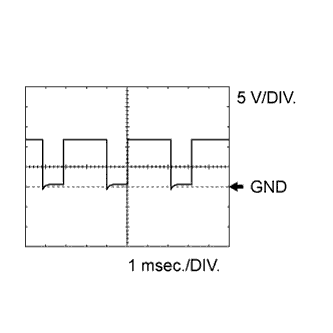
Item Content Symbols (Terminal No.) T19-9 (SL1+) - T19-8 (SL1-) Tool Setting 5 V/DIV., 1 msec./DIV. Condition Engine is idling -
Waveform 2 (Reference)
Item Content Symbols (Terminal No.) T19-7 (SL2+) - T19-6 (SL2-) Tool Setting 5 V/DIV., 1 msec./DIV. Condition Engine is idling -
Waveform 3 (Reference)
Item Content Symbols (Terminal No.) T19-20 (SLT+) - T19-19 (SLT-) Tool Setting 5 V/DIV., 1 msec./DIV. Condition Engine is idling -
Waveform 4 (Reference)
Item Content Symbols (Terminal No.) T19-22 (SLU+) - T19-21 (SLU-) Tool Setting 5 V/DIV., 1 msec./DIV. Condition 4th (lock-up) or 5th (lock-up) gear -
Waveform 5 (Reference)
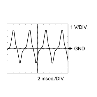
Item Content Symbols (Terminal No.) T19-3 (NT+) - T19-2 (NT-) Tool Setting 1 V/DIV., 2 msec./DIV. Condition Engine is idling -
Waveform 6 (Reference)
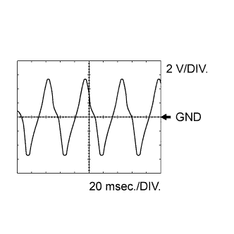
Item Content Symbols (Terminal No.) T19-30 (SP2+) - T19-29 (SP2-) Tool Setting 2 V/DIV., 20 msec./DIV. Condition Vehicle speed 20 km/h (12 mph) -
Waveform 7 (Reference)
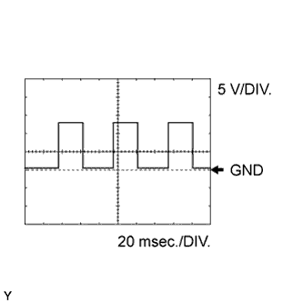
Item Content Symbols (Terminal No.) T38-25 (SPD1) - T19-1 (E1) Tool Setting 5 V/DIV., 20 msec./DIV. Condition Rear wheel turning slowly -
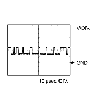
Waveform 8 (Reference)
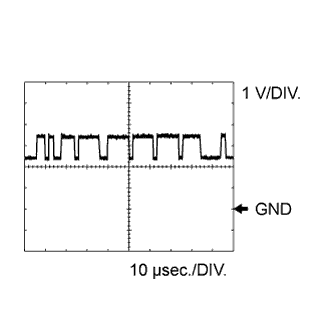
Item Content Symbols (Terminal No.) E24-24 (CAN+) - E25-1 (E1)*1
E6-22 (CAN+) - E7-7 (E1)*2
T38-21 (CAN+) - T19-1 (E1)
Tool Setting 1 V/DIV., 10 msec./DIV. Condition Ignition switch ON
-
*1: w/ DPF
-
*2: w/o DPF
-
-
Waveform 9 (Reference)
Item Content Symbols (Terminal No.) E24-18 (CAN-) - E25-1 (E1)*1
E6-21 (CAN-) - E7-7 (E1)*2
T38-20 (CAN-) - T19-1 (E1)
Tool Setting 1 V/DIV., 10 msec./DIV. Condition Ignition switch ON
-
*1: w/ DPF
-
*2: w/o DPF
-