INTERCOOLER INSTALLATION
PROCEDURE
-
TEMPORARILY INSTALL INTERCOOLER ASSEMBLY (for Type A)
Note
If temporary installation is not performed, parts may not be correctly positioned. As a result, connecting parts may not be airtight.
-
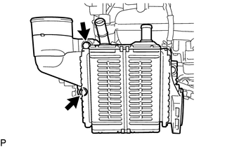
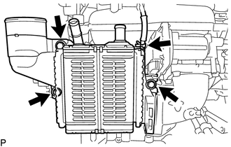
Temporarily install the intercooler assembly to the intercooler support bracket sub-assembly by hand with the 2 bolts in the position shown in the illustration.
-
Install the 3 gaskets to the intake manifold, intercooler assembly and No. 2 air tube.
Tech Tips
Check that the gasket is securely fitted into the installation groove.
-
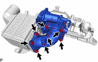
Install the throttle body with motor assembly and No. 2 air tube to the intake manifold with the 4 bolts.
- Torque:
- 10 N*m { 102 kgf*cm, 7 ft.*lbf }
-
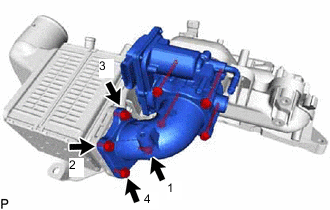
Temporarily install the No. 2 air tube with the 4 bolts, and then tighten them to the specified torque in the order shown in the illustration.
- Torque:
- 10 N*m { 102 kgf*cm, 7 ft.*lbf }
-
Tighten the 2 bolts of the intercooler assembly.
- Torque:
- 9.3 N*m { 95 kgf*cm, 82 in.*lbf }
-
Remove the 8 bolts, No. 2 air tube and throttle body with motor assembly.
Note
Do not loosen the installation bolts of the intercooler assembly.
-
Remove the 3 gaskets from the intake manifold, intercooler assembly and No. 2 air tube.
-
-
INSTALL INTERCOOLER ASSEMBLY
-
Install a new gasket to the intercooler assembly.
Tech Tips
Check that the gasket is securely fitted into the installation groove.
-
for Type A:
Install the intercooler assembly to the intercooler support bracket sub-assembly with the bolt in the position shown in the illustration.
- Torque:
- 9.3 N*m { 95 kgf*cm, 82 in.*lbf }
-
for Type B:
Install the intercooler assembly to the intercooler support bracket sub-assembly with the 3 bolts.
- Torque:
- 9.3 N*m { 95 kgf*cm, 82 in.*lbf }
-
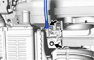
Connect the No. 1 vacuum transmitting hose to the intercooler assembly with the hose clip.
-
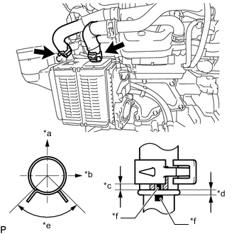
*a Front of Vehicle *b Right Side of Vehicle *c 2.0 to 7.0 mm (0.0787 to 0.275 in.) *d Insert Until Hose Contacts Stopper *e Hose Clamp Claw Range *f Paint Mark Connect the No. 8 water by-pass hose and No. 9 water by-pass hose to the intercooler assembly with the 2 clamps.
Tech Tips
Install the water by-pass hoses and hose clamps as shown in the illustration.
-
for Type B:
Temporarily connect the No. 2 air tube to the intercooler assembly with the 4 bolts in the sequence shown in the illustration, and then tighten the bolts at the specified torque.
- Torque:
- 10 N*m { 102 kgf*cm, 7 ft.*lbf }
-
-
INSTALL THROTTLE BODY WITH MOTOR ASSEMBLY (for Type A)
-
TEMPORARILY TIGHTEN PROPELLER SHAFT WITH CENTER BEARING ASSEMBLY (for AWD)
-
INSTALL PROPELLER WITH CENTER BEARING SHAFT ASSEMBLY (for AWD)
-
INSTALL NO. 1 AIR TUBE
-
Install the No. 1 air tube to the cylinder head sub-assembly with the 2 bolts.
- Torque:
- 21 N*m { 214 kgf*cm, 15 ft.*lbf }
-
Connect the No. 2 air hose to the intercooler assembly and tighten the hose clamp to secure the hose.
- Torque:
- 6.3 N*m { 64 kgf*cm, 56 in.*lbf }
-
Connect the No. 1 air hose to the intake air resonator and tighten the clamp to secure the hose.
- Torque:
- 6.3 N*m { 64 kgf*cm, 56 in.*lbf }
-
Connect the No. 3 PCV hose to the cylinder head cover sub-assembly with the hose clamp to secure the hose.
-
Connect the No. 2 fuel vapor feed hose with the clamp.
-
Connect the vacuum hose with the clamp.
-
-
INSTALL INTAKE AIR CONNECTOR
-
INSTALL AIR CLEANER CASE SUB-ASSEMBLY
-
INSTALL AIR CLEANER FILTER ELEMENT SUB-ASSEMBLY
-
INSTALL AIR CLEANER CAP WITH AIR CLEANER HOSE
-
INSTALL NO. 1 ENGINE COVER SUB-ASSEMBLY
-
INSTALL FRONT FLOOR COVER CENTER LH
-
ADD COOLANT
-
ADD COOLANT (for Intercooler)
-
INSPECT FOR COOLANT LEAK
-
INSPECT FOR COOLANT LEAK (for Intercooler)
-
INSTALL NO. 1 ENGINE UNDER COVER