BATTERY CURRENT SENSOR INSPECTION
PROCEDURE
CHECK BATTERY CURRENT SENSOR ASSEMBLY
Check the battery current sensor assembly.
-
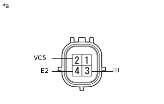
*a
Component without harness connected
(Battery Current Sensor)
Measure the resistance according to the value(s) in the table below.
Standard Resistance
Tester Connection
Condition
Specified Condition
2 (VC5) - 4 (E2)
Always
0.1 to 10 kΩ
2 (VC5) - 3 (IB)
Always
Below 0.5 kΩ
3 (IB) - 4 (E2)
Always
0.05 to 10 kΩ
If the result is not as specified, replace the battery current sensor assembly.
-
Check the battery temperature sensor.
-
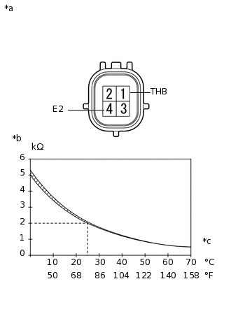
*a
Component without harness connected
(Battery Current Sensor)
*b
Resistance
*c
Temperature
Measure the resistance according to the value(s) in the table below.
Standard Resistance
Tester Connection
Condition
Specified Condition
1 (THB) - 4 (E2)
20 to 30°C (68 to 86°F)
1.5 to 2.5 kΩ
Tip:As the temperature increases, the resistance decreases (refer to the graph).
The battery temperature sensor is part of the battery current sensor assembly.
If the result is not as specified, replace the battery current sensor assembly.
-