STEERING GEAR REMOVAL
PROCEDURE
ALIGN FRONT WHEELS FACING STRAIGHT AHEAD
SECURE STEERING WHEEL
-
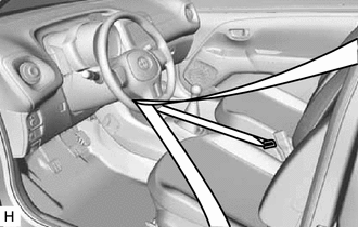
Secure the steering wheel with the seat belt in order to prevent rotation.
Tip:This operation is useful to prevent damage to the spiral cable.
-
REMOVE STEERING COLUMN HOLE COVER PLATE
SEPARATE NO. 2 STEERING INTERMEDIATE SHAFT ASSEMBLY
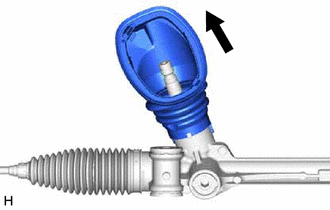
SEPARATE NO. 1 STEERING COLUMN HOLE COVER SUB-ASSEMBLY
-
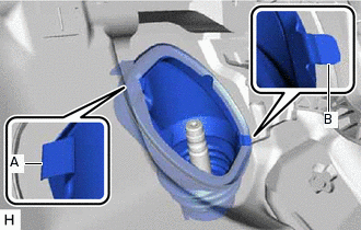
Disengage the clip (A) from the vehicle body.
Note:Do not damage the clip (A).
Disengage the clip (B) from the vehicle body and separate the No. 1 steering column hole cover sub-assembly.
Note:Do not damage the clip (B).
-
REMOVE FRONT WHEELS
REMOVE FRONT EXHAUST PIPE ASSEMBLY
for 1KR-FE:Click hereClick here
for 1PP:Click here
SEPARATE TIE ROD END SUB-ASSEMBLY LH
Remove the cotter pin and nut.
-
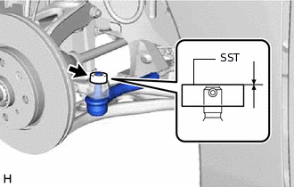
Install SST to the tie rod end sub-assembly LH.
09960-20010
09961-02060
Note:Make sure that the upper ends of the tie rod end sub-assembly LH and SST are aligned.
Secure SST using a string.
Note:Be sure to tighten the string firmly to secure SST to the steering knuckle to prevent SST from falling off.
Using SST, separate the tie rod end sub-assembly LH from the steering knuckle.
09960-20010
09961-02010
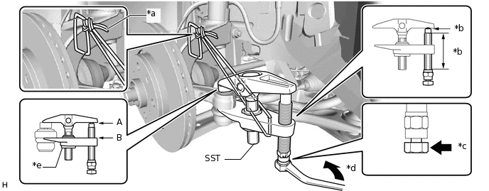
*a
String
*b
Molybdenum grease application area
*c
Place wrench here
*d
Turn
*e
Center Nut
-
-
CAUTION:Apply molybdenum grease to the bolt threads and the tip of SST.
Note:Be sure to tighten the string firmly to secure SST to the steering knuckle to prevent SST from falling off.
Install SST with the center nut so that A and B shown in the illustration are parallel. Otherwise, the ball joint dust cover may be damaged.
Be sure to place the wrench on the part indicated in the illustration.
Do not damage the front disc brake dust cover.
Do not damage the ball joint dust cover.
Do not damage the steering knuckle.
SEPARATE TIE ROD END SUB-ASSEMBLY RH
Tip:Perform the same procedure as for the LH side.
SEPARATE FRONT STABILIZER BAR (for LH Side)
SEPARATE FRONT STABILIZER BAR (for RH Side)
Tip:Perform the same procedure as for the LH side.
SEPARATE FRONT LOWER NO. 1 SUSPENSION ARM SUB-ASSEMBLY LH
SEPARATE FRONT LOWER NO. 1 SUSPENSION ARM SUB-ASSEMBLY RH
Tip:Perform the same procedure as for the LH side.
REMOVE FRONT SUSPENSION CROSSMEMBER SUB-ASSEMBLY
REMOVE NO. 1 STEERING COLUMN HOLE COVER SUB-ASSEMBLY
-
Remove the No. 1 steering column hole cover sub-assembly from the steering link assembly.
-
REMOVE STEERING LINK ASSEMBLY
-
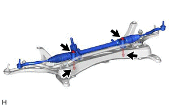
Remove the 2 bolts, 2 nuts and steering link assembly from the front suspension crossmember sub-assembly.
Note:Because the nut has its own stopper, do not turn the nut. Loosen the bolt with the nut secured.
-
SECURE STEERING LINK ASSEMBLY
-
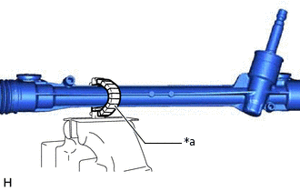
*a
Protective Tape
Using SST, secure the steering link assembly in a vise.
09612-00012
Tip:Wrap SST with protective tape before use.
-
REMOVE TIE ROD END SUB-ASSEMBLY LH
-
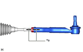
*a
Matchmark
Put matchmarks on the tie rod end sub-assembly LH and steering gear assembly.
Remove the tie rod end sub-assembly LH and lock nut.
-
REMOVE TIE ROD END SUB-ASSEMBLY RH
Tip:Perform the same procedure as for the LH side.