ВЫХОДНОЙ ВАЛ СНЯТИЕ
-
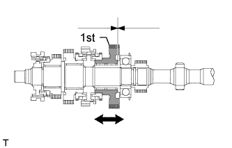
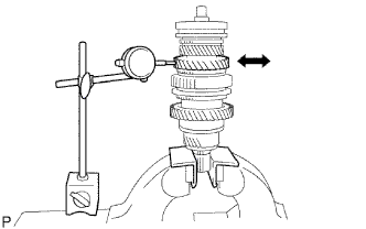
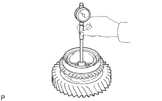
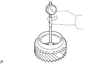
INSPECT 1ST GEAR THRUST CLEARANCE
-
Using a dial indicator, measure the thrust clearance.
Standard clearance 0.10 to 0.25 mm (0.0039 to 0.0098 in.)
-
-
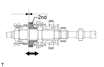
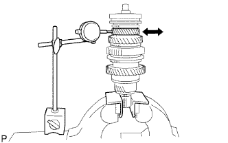
INSPECT 2ND GEAR THRUST CLEARANCE
-
Using a dial indicator, measure the thrust clearance.
Standard clearance 0.10 to 0.25 mm (0.0039 to 0.0098 in.)
-
-
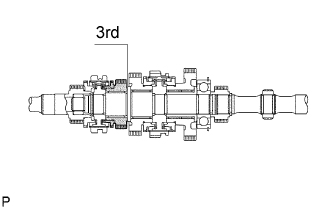
INSPECT 3RD GEAR THRUST CLEARANCE
-
Using a feeler gauge, measure the thrust clearance.
Standard clearance 0.10 to 0.25 mm (0.0039 to 0.0098 in.)
-
-
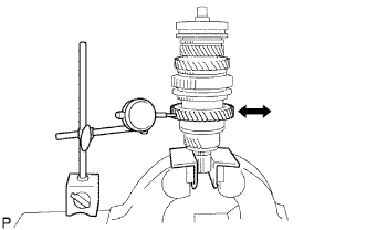
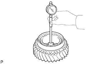
INSPECT 1ST GEAR RADIAL CLEARANCE
-
Using a dial indicator, measure the radial clearance.
Standard clearance 0.009 to 0.056 mm (0.0004 to 0.0022 in.)
-
-
INSPECT 2ND GEAR RADIAL CLEARANCE
-
Using a dial indicator, measure the radial clearance.
Standard clearance 0.008 to 0.034 mm (0.0003 to 0.0013 in.)
-
If the clearance is not as specified, replace the 2nd gear needle roller bearing.
-
-
-
INSPECT 3RD GEAR RADIAL CLEARANCE
-
Using a dial indicator, measure the radial clearance.
Standard clearance 0.008 to 0.034 mm (0.0003 to 0.0013 in.)
-
If the clearance is not as specified, replace the 3rd gear needle roller bearing.
-
-
-
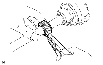
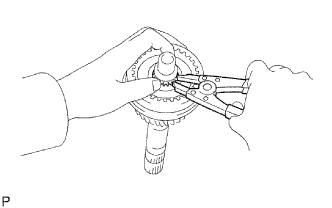
REMOVE SPEEDOMETER DRIVE GEAR
-
Using a snap ring expander, remove the snap ring.
-
Remove the drive gear.
-
Using a magnetic finger, remove the ball.
-
Using a snap ring expander, remove the other snap ring.
-
-
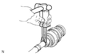
REMOVE 1ST GEAR
-
Using 2 screwdrivers and a hammer, tap out the snap ring from the output shaft.
-
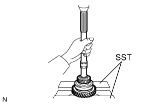
Using SST and a press, press out the 5th gear, center bearing, 1st gear, 1st gear needle roller bearing and 1st gear bearing inner race from the output shaft.
- SST
- 09527-10011
-
-
REMOVE NO. 1 SYNCHRONIZER RING (for 1st Gear)
-
Remove the No. 1 synchronizer ring (for the 1st gear) from the No. 1 clutch hub.
-
-
REMOVE 1ST GEAR BEARING INNER RACE LOCK BALL
-
Using a magnetic finger, remove the lock ball.
-
-
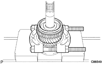
REMOVE 2ND GEAR
-
Using SST and a press, press out the No. 1 clutch hub reverse gear, No. 1 synchronizer ring and 2nd gear.
- SST
- 09950-00020
-
-
REMOVE NO. 1 SYNCHRONIZER RING (for 2nd Gear)
-
Remove the No. 1 synchronizer ring from the 2nd gear.
-
-
REMOVE 2ND GEAR NEEDLE ROLLER BEARING
-
Remove the needle roller bearing from the output shaft.
-
-
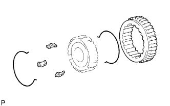
REMOVE NO. 1 TRANSMISSION CLUTCH HUB
-
Remove the 2 synchromesh shifting key springs.
-
Remove the reverse gear and 3 synchromesh shifting keys from the transmission clutch hub.
-
-
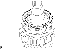
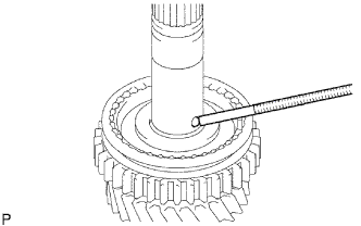
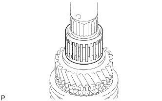
REMOVE 3RD GEAR
-
Using a snap ring expander, remove the snap ring from the output shaft.
-
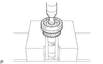
Using a press, press out the No. 2 clutch hub and 3rd gear.
-
-
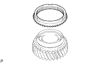
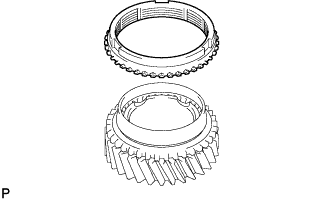
REMOVE NO. 2 SYNCHRONIZER RING
-
Remove the synchronizer ring from the 3rd gear.
-
-
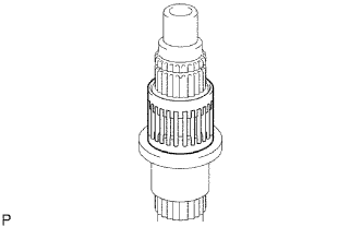
REMOVE 3RD GEAR NEEDLE ROLLER BEARING
-
Remove the needle roller bearing from the output shaft.
-
-
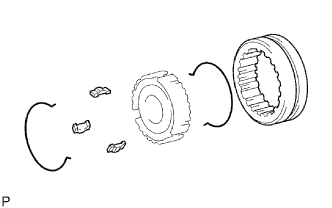
REMOVE NO. 2 TRANSMISSION CLUTCH HUB
-
Remove the 2 synchromesh shifting key springs.
-
Remove the transmission hub sleeve and 3 synchromesh shifting keys from the transmission clutch hub.
-
-
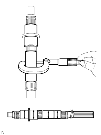
INSPECT OUTPUT SHAFT
-
Using a micrometer, measure the outside diameter of the output shaft journal surface.
Standard outside diameter Position Specified Condition Part A 34.984 to 35.000 mm (1.3773 to 1.3780 in.) Part B 37.984 to 38.000 mm (1.4945 to 1.4960 in.) Part C 30.384 to 30.400 mm (1.1962 to 1.1968 in.) Part D 30.002 to 30.018mm (1.1812 to 1.1818 in.)
-
If the outside diameter is not as specified, replace the output shaft.
-
-
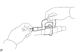
Using a micrometer, measure the flange thickness.
Standard thickness 4.80 to 5.20 mm (0.1890 to 0.2047 in.) Minimum thickness 4.80 mm (0.1890 in.)
-
If the thickness is less than the minimum, replace the output shaft.
-
-
-
INSPECT 1ST GEAR BEARING INNER RACE
-
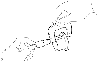
Using a micrometer, measure the inner race thickness.
Standard thickness 4.00 to 4.20 mm (0.1575 to 0.1654 in.) Minimum thickness 4.00 mm (0.1575 in.)
-
If the thickness is less than the minimum, replace the 1st gear bearing inner race.
-
-
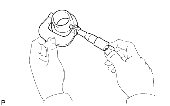
Using a micrometer, measure the outside diameter of the inner race.
Standard outside diameter 38.985 to 39.000 mm (1.5348 to 1.5354 in.) Minimum outside diameter 38.985 (1.5348 in.)
-
If the outside diameter is less than the minimum, replace the 1st gear bearing inner race.
-
-
-
INSPECT NO. 1 SYNCHRONIZER RING (For 1st Gear)
-
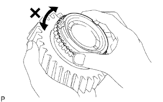
Coat the 1st gear cone with gear oil. Check the braking effect of the No. 1 synchronizer ring. Fit the ring to the shaft cone. Apply pressure to the ring and attempt to turn it in both directions. Check that the ring locks.
-
If the braking effect is insufficient, apply a small amount of fine lapping compound between the No. 1 synchronizer ring and the 1st gear cone. Lightly rub the No. 1 synchronizer ring and the 1st gear cone together.
Note
Ensure the fine lapping compound is completely washed off after rubbing.
-
-
Check the braking effect of the No. 1 synchronizer ring again.
-
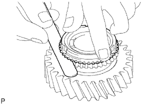
Using a feeler gauge, measure the clearance between the No. 1 synchronizer ring back and 1st gear spline end.
Standard clearance 1.00 to 2.00 mm (0.0394 to 0.0787 in.)
-
If the clearance is not as specified, replace the No. 1 synchronizer ring and apply a small amount of fine lapping compound on the 1st gear cone.
Note
Ensure the fine lapping compound is completely washed off after rubbing.
-
-
-
INSPECT NO. 1 SYNCHRONIZER RING (for 2nd Gear)
-
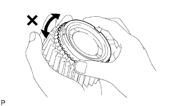
Coat the 2nd gear cone with gear oil. Check the braking effect of the No. 1 synchronizer ring. Fit the ring to the shaft cone. Apply pressure to the ring and attempt to turn it in both directions. Check that the ring locks.
-
If the braking effect is insufficient, apply a small amount of fine lapping compound between the No. 1 synchronizer ring and the 2nd gear cone. Lightly rub the No. 1 synchronizer ring and the 2nd gear cone together.
Note
Ensure the fine lapping compound is completely washed off after rubbing.
-
-
Check the braking effect of the No. 1 synchronizer ring again.
-
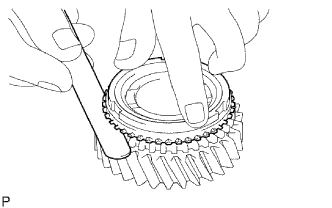
Using a feeler gauge, measure the clearance between the No. 1 synchronizer ring back and 2nd gear spline end.
Standard clearance 1.00 to 2.00 mm (0.0394 to 0.0787 in.)
-
If the clearance is not as specified, replace the No. 1 synchronizer ring, and apply a small amount of fine lapping compound on the 2nd gear cone.
Note
Ensure the fine lapping compound is completely washed off after rubbing.
-
-
-
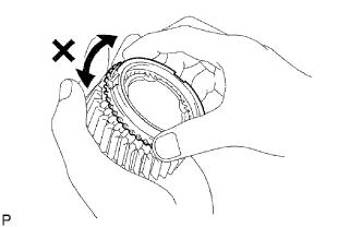
INSPECT NO. 2 SYNCHRONIZER RING
-
Coat the 3rd gear cone with gear oil. Check the braking effect of the No. 2 synchronizer ring. Fit the ring to the shaft cone. Apply pressure to the ring and attempt to turn it in both directions. Check that the ring locks.
-
If the braking effect is insufficient, apply a small amount of fine lapping compound between the No. 2 synchronizer ring and the 3rd gear cone. Lightly rub the No. 2 synchronizer ring and the 3rd gear cone together.
Note
Ensure the fine lapping compound is completely washed off after rubbing.
-
-
Check the braking effect of the No. 2 synchronizer ring again.
-
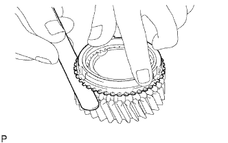
Using a feeler gauge, measure the clearance between the No. 2 synchronizer ring back and 3rd gear spline end.
Standard clearance 1.0 to 2.0 mm (0.0394 to 0.0787 in.)
-
If the clearance is not as specified, replace the No. 2 synchronizer ring and apply a small amount of fine lapping compound on the 3rd gear cone.
Note
Ensure the fine lapping compound is completely washed off after rubbing.
-
-
-
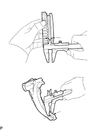
INSPECT REVERSE GEAR
-
Using a vernier caliper, measure the clearance between the reverse gear and No. 1 gear shift fork.
Standard clearance 0.15 to 0.35 mm (0.0059 to 0.0138 in.) Minimum clearance 0.35 mm (0.0138 in.)
-
If the clearance is less than the minimum, replace the No. 1 gear shift fork and reverse gear.
-
-
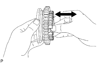
Check that the No. 1 transmission clutch hub and reverse gear slide smoothly.
-
Check that the spline gear's edges of the reverse gear are not worn down.
-
-
INSPECT NO. 2 TRANSMISSION HUB SLEEVE
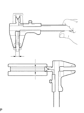
-
Using a vernier caliper, measure the No. 2 hub sleeve and No. 2 gear shift fork as shown in the illustration.
Standard clearance 0.15 to 0.35 mm (0.0059 to 0.0138 in.)
-
If the clearance is not as specified, replace the transmission hub sleeve and the No. 2 gear shift fork.
-
-
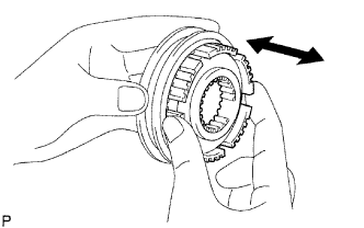
Check the sliding condition between the No. 2 hub sleeve and No. 2 clutch hub.
-
Check that the spline gear's edges of the No. 2 transmission hub sleeve are not worn down.
-
-
INSPECT 1ST GEAR
-
Using a cylinder gauge, measure the inside diameter of the 1st gear.
Standard inside diameter 44.015 to 44.040 mm (1.7329 to 1.7339 in.) Maximum inside diameter 44.040 mm (1.7339 in.)
-
If the inside diameter is greater than the maximum, replace the 1st gear.
-
-
-
INSPECT 2ND GEAR
-
Using a cylinder gauge, measure the inside diameter of the 2nd gear.
Standard inside diameter 44.015 to 44.040 mm (1.7329 to 1.7339 in.) Maximum inside diameter 44.040 mm (1.7339 in.)
-
If the inside diameter is greater than the maximum, replace the 2nd gear.
-
-
-
INSPECT 3RD GEAR
-
Using a cylinder gauge, measure the inside diameter of the 3rd gear.
Standard inside diameter 44.015 to 44.040 mm (1.7329 to 1.7339 in.) Maximum inside diameter 44.040 mm (1.7339 in.)
-
If the inside diameter is greater than the maximum, replace the 3rd gear.
-
-