POWER OUTLET SOCKET REMOVAL
PROCEDURE
-
PRECAUTION
Note
After turning the power switch off, waiting time may be required before disconnecting the cable from the negative (-) auxiliary battery terminal. Therefore, make sure to read the disconnecting the cable from the negative (-) auxiliary battery terminal notices before proceeding with work Click here.
-
REMOVE DECK BOARD ASSEMBLY
-
REMOVE NO. 1 DECK BOARD
-
REMOVE NO. 2 DECK BOARD
-
REMOVE REAR DECK FLOOR BOX
-
REMOVE DECK FLOOR BOX RH
-
DISCONNECT CABLE FROM NEGATIVE AUXILIARY BATTERY TERMINAL
Note
When disconnecting the cable, some systems need to be initialized after the cable is reconnected Click here.
-
REMOVE CONSOLE BOX ASSEMBLY
-
REMOVE INTEGRATION CONTROL AND PANEL
-
REMOVE INSTRUMENT PANEL BOX ASSEMBLY
-
REMOVE LOWER INSTRUMENT PANEL FINISH PANEL SUB-ASSEMBLY
-
REMOVE NO. 3 POWER OUTLET SOCKET ASSEMBLY (for LHD)
-
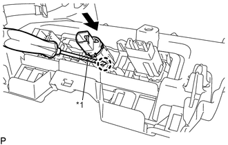
Text in Illustration *1 Protective Tape Using a screwdriver, disengage the claw and remove the No. 3 power outlet socket assembly as shown in the illustration.
Tech Tips
Tape the screwdriver tip before use.
-
-
REMOVE NO. 2 POWER OUTLET SOCKET COVER (for LHD)
-
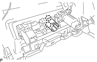
Disengage the 2 claws and remove the No. 2 power outlet socket cover.
-
-
REMOVE NO. 3 POWER OUTLET SOCKET ASSEMBLY (for RHD)
-
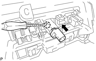
Text in Illustration *1 Protective Tape Using a screwdriver, disengage the claw and remove the No. 3 power outlet socket assembly as shown in the illustration.
Tech Tips
Tape the screwdriver tip before use.
-
-
REMOVE NO. 2 POWER OUTLET SOCKET COVER (for RHD)
-
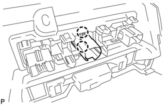
Disengage the 2 claws and remove the No. 2 power outlet socket cover.
-