TOUCH SELECT 2-4 AND HIGH-LOW SYSTEM, Diagnostic DTC:P17A4
| DTC Code | DTC Name |
|---|---|
| P17A4 | Automatic Disconnecting Differential Motor Limit Switch Circuit |
DESCRIPTION
When the A.D.D. actuator switches between 2WD and 4WD, the DL1 and DL2 terminals of the limit switch and ADD terminal of the A.D.D. position switch change to one of the following ON/OFF combinations listed in the table below.
| Terminal | In 2WD | Switching between 2WD and 4WD | In 4WD | |
|---|---|---|---|---|
| DL1 | ON (GND) | ON (GND) | OFF (OPEN) | |
| DL2 | OFF (OPEN) | ON (GND) | ON (GND) | |
| ADD | OFF (OPEN) | OFF (OPEN) | ON (GND) | ON (GND) |
A malfunction is detected depending on the combination of the 3 circuits that make up the limit switch and A.D.D. position switch.
| DTC No. | Detection Item | DTC Detection Condition | Trouble Area |
|---|---|---|---|
| P17A4 | Automatic Disconnecting Differential Motor Limit Switch Circuit |
|
|
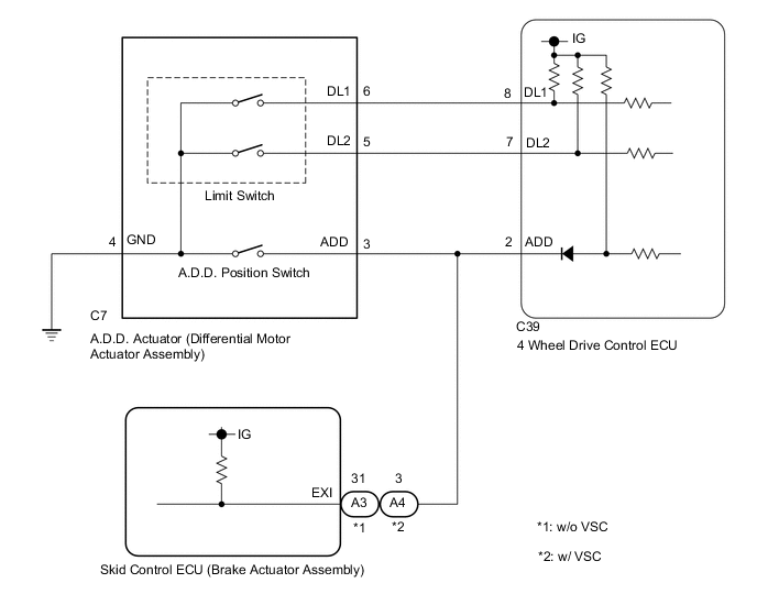
WIRING DIAGRAM
PROCEDURE
-
CHECK HARNESS AND CONNECTOR (4 WHEEL DRIVE CONTROL ECU - DIFFERENTIAL MOTOR ACTUATOR ASSEMBLY)
-
Disconnect the C39 4 wheel drive control ECU connector.
-
Disconnect the C7 A.D.D. actuator (differential motor actuator assembly) connector.
-
w/o VSC:
Disconnect the A3 skid control ECU (brake actuator assembly) connector.
w/ VSC:
Disconnect the A4 skid control ECU (brake actuator assembly) connector.
-
Measure the resistance according to the value(s) in the table below.
Standard Resistance Tester Connection Condition Specified Condition C39-8 (DL1) - C7-6 (DL1) Always Below 1 Ω C39-7 (DL2) - C7-5 (DL2) Always Below 1 Ω C39-2 (ADD) - C7-3 (ADD) Always Below 1 Ω C7-4 (GND) - Body ground Always Below 1 Ω C39-8 (DL1) or C7-6 (DL1) - Body ground Always 10 kΩ or higher C39-7 (DL2) or C7-5 (DL2) - Body ground Always 10 kΩ or higher C39-2 (ADD) or C7-3 (ADD) - Body ground Always 10 kΩ or higher Result Proceed to OK NG
NG 
REPAIR OR REPLACE HARNESS OR CONNECTOR
OK 
-
-
INSPECT DIFFERENTIAL MOTOR ACTUATOR ASSEMBLY (LIMIT SWITCH AND A.D.D. POSITION SWITCH)
-
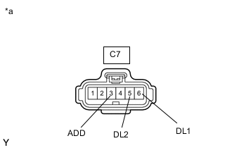
*a Front view of wire harness connector
(to A.D.D. Actuator (Differential Motor Actuator Assembly))
Disconnect the C7 A.D.D. actuator (differential motor actuator assembly) connector.
-
w/o VSC:
Disconnect the A3 skid control ECU (brake actuator assembly) connector.
w/ VSC:
Disconnect the A4 skid control ECU (brake actuator assembly) connector.
-
Measure the voltage according to the value(s) in the table below.
Standard Voltage Tester Connection Condition Specified Condition C7-6 (DL1) - Body ground Ignition switch ON 10 to 14 V C7-5 (DL2) - Body ground Ignition switch ON 10 to 14 V C7-3 (ADD) - Body ground Ignition switch ON 10 to 14 V Result Proceed to OK NG
OK
REPLACE DIFFERENTIAL MOTOR ACTUATOR ASSEMBLY Click here
NG
REPLACE 4 WHEEL DRIVE CONTROL ECU Click here
-