BRAKE ACTUATOR(w/o Vacuum Brake Booster) INSPECTION

PROCEDURE
-
INSPECT BRAKE ACTUATOR ASSEMBLY
-
Inspect the solenoid circuit.
-
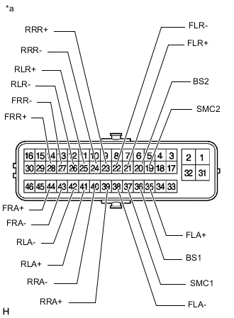
*a Component without harness connected
(Brake Actuator Assembly)
Measure the resistance according to the value(s) in the table below.
Tech Tips
Check the brake actuator assembly when it is cooled down.
Standard Resistance Tester Connection Condition Specified Condition A8-37 (SMC1) - A8-36 (BS1) Always 15.3 to 17.3 Ω A8-19 (SMC2) - A8-20 (BS2) Always 15.3 to 17.3 Ω A8-44 (FRA+) - A8-43 (FRA-) Always 3.6 to 4.2 Ω A8-28 (FRR+) - A8-27 (FRR-) Always 3.6 to 4.2 Ω A8-35 (FLA+) - A8-38 (FLA-) Always 3.6 to 4.2 Ω A8-21 (FLR+) - A8-22 (FLR-) Always 3.6 to 4.2 Ω A8-39 (RRA+) - A8-40 (RRA-) Always 3.6 to 4.2 Ω A8-41 (RLA+) - A8-42 (RLA-) Always 3.6 to 4.2 Ω A8-23 (RRR+) - A8-24 (RRR-) Always 4.4 to 5.0 Ω A8-25 (RLR+) - A8-26 (RLR-) Always 4.4 to 5.0 Ω If the result is not as specified, replace the brake actuator assembly.
-
-