REAR DRIVE SHAFT ASSEMBLY REMOVAL
CAUTION / NOTICE / HINT
Use the same procedure for the RH and LH sides.
The procedure listed below is for the LH side.
PROCEDURE
REMOVE REAR WHEEL
REMOVE TAIL EXHAUST PIPE ASSEMBLY
REMOVE REAR AXLE SHAFT NUT LH
DISCONNECT REAR SPEED SENSOR LH
REMOVE REAR SUSPENSION MEMBER BRACE LH
REMOVE REAR SUSPENSION ARM COVER LH (w/ Cover)
REMOVE REAR DRIVE SHAFT ASSEMBLY LH
-
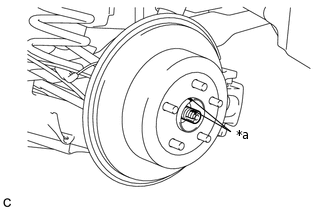
*a
Matchmark
Put matchmarks on the rear drive shaft assembly LH and rear axle hub and bearing assembly.
-
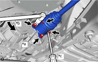
*a
Matchmark
*b
Turn
*c
Hold
Put matchmarks on the rear drive shaft assembly LH and differential side gear shaft sub-assembly.
Using a screwdriver or an equivalent, hold the differential side gear shaft sub-assembly as shown in the illustration.
Remove the 4 nuts and 4 washers.
Push the rear drive shaft inboard joint assembly LH toward the outside of the vehicle and disconnect the rear drive shaft assembly LH from the differential side gear shaft sub-assembly.
-
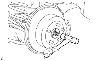
Using a plastic-faced hammer, remove the rear drive shaft assembly LH from the rear axle hub and bearing assembly.
Note:Do not damage the outboard joint boot.
Do not drop the rear drive shaft assembly LH.
Do not damage the rear speed sensor rotor.
If it is difficult to remove, tap the end of the rear drive shaft assembly LH using a brass bar and a hammer.
-