PARKING ASSIST MONITOR SYSTEM(w/ Side Monitor System), Diagnostic DTC:C1613
| DTC Code | DTC Name |
|---|---|
| C1613 | ACC Voltage is Low or High |
DESCRIPTION
This DTC is stored if the parking assist ECU judges as a result of its self check that the voltage received by terminal ACC is not normal.
DTC No. |
Detection Item |
DTC Detection Condition |
Trouble Area |
|---|---|---|---|
C1613 |
ACC Voltage is Low or High |
|
|
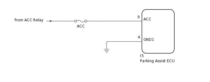
WIRING DIAGRAM
CAUTION / NOTICE / HINT
When "System initialising" is displayed on the parking assist ECU after the cable is disconnected from the negative (-) battery terminal, correct the steering angle neutral point (Click here).
Depending on the parts that are replaced or operations that are performed during vehicle inspection or maintenance, calibration of other systems as well as the parking assist monitor system may be needed (Click here).
Inspect the fuses for circuits related to this system before performing the following inspection procedure.
PROCEDURE
CHECK FOR DTC
Clear the DTCs.
Chassis > IPA/Parking Assist Monitor > Clear DTCs
Check for DTCs.
Chassis > IPA/Parking Assist Monitor > Trouble Codes
Result
Proceed to
OK
NG
OK
DTC C1613 is not output.
Tip:If the parking assist ECU cannot read the stored information when it is activated, allowing the ECU to store the information again may return the system to normal.
CHECK HARNESS AND CONNECTOR (PARKING ASSIST ECU - BATTERY AND BODY GROUND)
-
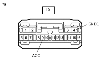
*a
Front view of wire harness connector
(to Parking Assist ECU)
Disconnect the parking assist ECU connector.
Measure the resistance according to the value(s) in the table below.
Standard Resistance
Tester Connection
Condition
Specified Condition
I5-4 (GND1) - Body ground
Always
Below 1 Ω
Measure the voltage according to the value(s) in the table below.
Standard Voltage
Tester Connection
Switch Condition
Specified Condition
I5-9 (ACC) - I5-4 (GND1)
Engine switch on (ACC)
10 to 16 V
Result
Result
OK
NG
NG REPAIR OR REPLACE HARNESS OR CONNECTOR
-