FRONT AXLE HUB REMOVAL
CAUTION / NOTICE / HINT
Use the same procedure for the RH side and LH side.
The following procedure is for the LH side.
PROCEDURE
REMOVE FRONT WHEEL
LOOSEN HEXALOBULAR SCREW
REMOVE FRONT AXLE SHAFT NUT
for 1KR-FE:Click here
for 1PP:Click here
SEPARATE FRONT SPEED SENSOR
-
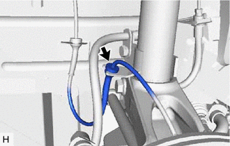
Separate the front speed sensor from the front shock absorber assembly bracket.
-
Remove the bolt and separate the front speed sensor from the steering knuckle.
Note:Prevent foreign matter from attaching to the front speed sensor tip.
Clean the speed sensor installation hole and the contact surfaces every time the front speed sensor is removed.
-
SEPARATE FRONT DISC BRAKE CALIPER ASSEMBLY
REMOVE FRONT DISC
SEPARATE TIE ROD END SUB-ASSEMBLY
SEPARATE FRONT STABILIZER BAR
-
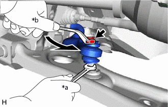
*a
Hold
*b
Turn
While holding the front stabilizer bolt with a wrench, remove the nut.
Remove the 2 No. 1 cushion retainers, 2 front stabilizer cushions and separate the front stabilizer bar.
-
SEPARATE FRONT LOWER NO. 1 SUSPENSION ARM SUB-ASSEMBLY
SEPARATE FRONT DRIVE SHAFT ASSEMBLY
-
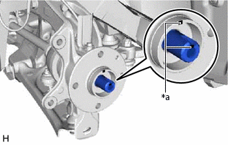
*a
Matchmark
Put matchmarks on the front drive shaft assembly and front axle hub sub-assembly.
Using a plastic hammer, separate the front drive shaft assembly from the front axle assembly.
Note:Do not push the front axle assembly further out of the vehicle than is necessary.
Do not damage the front drive shaft outboard joint boot.
Do not damage the magnetic seal of the front axle hub bearing.
Hang the front drive shaft assembly down with a piece of string or equivalent.
Tip:If it is difficult to separate the front drive shaft assembly from the front axle assembly, tap the end of the front drive shaft assembly using a brass bar and a hammer.
-
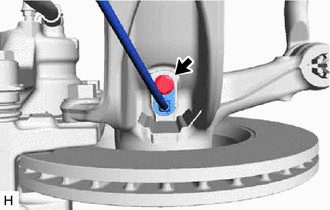
REMOVE FRONT AXLE ASSEMBLY
-
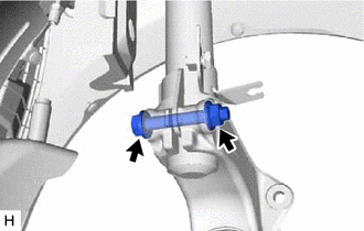
Remove the bolt and nut.
Note:When removing the nut, keep the bolt from rotating.
-
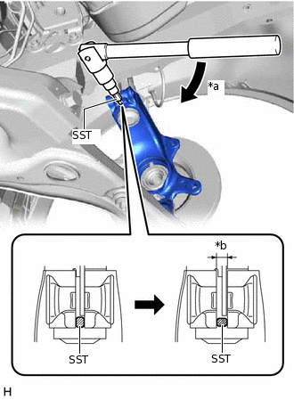
*a
Turn 90°
*b
Maximum 10 mm (0.394 in.)
Using SST, widen the steering knuckle slit.
09723-70010
Note:Do not widen the steering knuckle slit to more than 10 mm (0.394 in.).
Do not damage the steering knuckle slit.
Do not deform the bracket of the front shock absorber assembly.
Tip:When turning SST, use a 10 mm socket wrench.
Remove the front axle assembly from the front shock absorber assembly.
Remove SST.
Tip:Turn SST 90° to remove it.
-
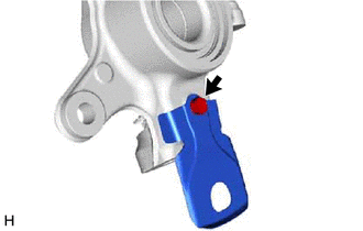
REMOVE SKID CONTROL SENSOR COVER
-
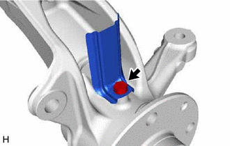
Using a T30 "TORX" socket wrench, remove the bolt and skid control sensor cover from the steering knuckle.
-
REMOVE FRONT AXLE HUB SUB-ASSEMBLY
Secure the front axle assembly between aluminum plates in a vise.
Note:Do not overtighten the vise.
-
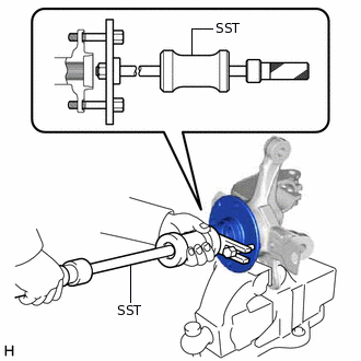
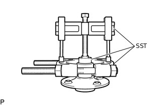
Using SST and 2 bolts (underhead length: 70 mm), remove the front axle hub sub-assembly from the steering knuckle.
09520-24010
-
Using SST, remove the front axle hub bearing inner race (outside) from the front axle hub sub-assembly.
09950-00020
09950-50013
09951-05010
09952-05010
09953-05020
09954-05021
09955-05040
09957-04010
09950-60010
09951-00360
REMOVE FRONT STEERING KNUCKLE HEAT INSULATOR
-
Using a T30 "TORX" socket wrench, remove the bolt and front steering knuckle heat insulator from the steering knuckle.
-
REMOVE FRONT AXLE HUB HOLE SNAP RING
-
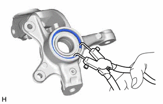
Using snap ring pliers, remove the front axle hub hole snap ring.
-
REMOVE FRONT AXLE HUB BEARING
-
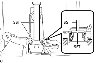
Using SST and a press, remove the front axle hub bearing from the steering knuckle.
09950-60010
09951-00470
09950-70010
09951-07100
Note:Position the steering knuckle horizontally.
-