SFI SYSTEM(w/o Canister Pump Module), Diagnostic DTC:P23AA72, P2C2972
| DTC Code | DTC Name |
|---|---|
| P23AA72 | Turbocharger/Supercharger Bypass Valve "A" Actuator Stuck Open |
| P2C2972 | Turbocharger/Supercharger Bypass Valve "B" Actuator Stuck Open |
DESCRIPTION
Refer to DTC P003312.
| DTC No. | Detection Item | DTC Detection Condition | Trouble Area | MIL | Memory | Note |
|---|---|---|---|---|---|---|
| P23AA72 | Turbocharger/Supercharger Bypass Valve "A" Actuator Stuck Open | Either of the following conditions is met (1 trip detection logic).
|
|
- | DTC stored | SAE: P23AA |
| P2C2972 | Turbocharger/Supercharger Bypass Valve "B" Actuator Stuck Open | Either of the following conditions is met (1 trip detection logic).
|
|
- | DTC stored | SAE: P2C29 |
MONITOR DESCRIPTION
- Air By-pass Valve Assembly Stuck Open
When the accelerator pedal is fully released while the vehicle is stopped after engine warm-up, the ECM opens and closes the air by-pass valve assembly and checks the operation.
At that time, if the operating current value when the air by-pass valve assembly is opened differs from the normal state, the ECM judges that the air by-pass valve assembly is stuck open and stores a DTC.
- Dual Intake Air Flow Difference Malfunction
When the difference between the intake air flow between bank 1 and bank 2 is the threshold value or more when boosting, the ECM determines that there is a malfunction in the intake and exhaust system and outputs a DTC.
CONFIRMATION DRIVING PATTERN
-
Connect the GTS to the DLC3.
-
Turn the engine switch on (IG).
-
Turn the GTS on.
-
Clear the DTCs (even if no DTCs are stored, perform the clear DTC procedure).
-
Start the engine and warm it up until the engine coolant temperature reaches 75°C (167°F) or higher.
-
Turn the engine switch off and wait for at least 30 seconds.
-
Turn the engine switch on (IG).
-
Turn the GTS on.
-
Start the engine.
-
Idle the engine for 1 minute or more.
-
Enter the following menus: Powertrain / Engine / Trouble Codes.
-
Read the pending DTCs.
Tech Tips
-
If a pending DTC is output, the system is malfunctioning.
-
If a pending DTC is not output, perform the following procedure.
-
-
Enter the following menus: Powertrain / Engine / Utility / All Readiness.
-
Input the DTC: P23AA72 or P2C2972.
-
Check the DTC judgment result.
GTS Display Description NORMAL
-
DTC judgment completed
-
System normal
ABNORMAL
-
DTC judgment completed
-
System abnormal
INCOMPLETE
-
DTC judgment not completed
-
Perform driving pattern after confirming DTC enabling conditions
Tech Tips
-
If the judgment result is NORMAL, the system is normal.
-
If the judgment result is ABNORMAL, the system is malfunctioning.
-
CAUTION / NOTICE / HINT
Note
Inspect the fuses for circuits related to this system before performing the following procedure.
Tech Tips
-
Read Freeze Frame Data using the GTS. The ECM records vehicle and driving condition information as Freeze Frame Data the moment a DTC is stored. When troubleshooting, Freeze Frame Data can help determine if the vehicle was moving or stationary, if the engine was warmed up or not, if the air fuel ratio was lean or rich, and other data from the time the malfunction occurred.
-
Bank 1 refers to the bank that includes the No. 1 cylinder*.
*: The No. 1 cylinder is the cylinder which is farthest from the transmission.
-
Bank 2 refers to the bank that does not include the No. 1 cylinder.
DTC Suspected Area P23AA72 Bank 1 P2C2972 Bank 2
PROCEDURE
-
CHECK ANY OTHER DTCS OUTPUT (IN ADDITION TO DTC P23AA72 OR P2C2972)
-
Connect the GTS to the DLC3.
-
Turn the engine switch on (IG).
-
Turn the GTS on.
-
Enter the following menus: Powertrain / Engine / Trouble Codes.
-
Read the DTCs.
Powertrain > Engine > Trouble CodesResult Result Proceed to DTC P23AA72 or P2C2972 is output A Both DTC P23AA72 and P2C2972 are output B DTC P23AA72 or P2C2972 and other DTCs are output C Tech Tips
If any DTCs other than P23AA72 or P2C2972 are output, troubleshoot those DTCs first.
B 
CLEAR DTC Click here
C 
GO TO DTC CHART Click here
A 
-
-
PERFORM ACTIVE TEST USING GTS (ACTIVATE THE AIR BYPASS VALVE OR ACTIVATE THE AIR BYPASS VALVE BANK2)
-
Remove the air by-pass valve assembly.
Tech Tips
Do not disconnect the connector.
-
Connect the GTS to the DLC3.
-
Turn the engine switch on (IG).
-
Turn the GTS on.
-
Enter the following menus: Powertrain / Engine / Active Test / Activate the Air Bypass Valve.
Powertrain > Engine > Active TestTester Display Activate the Air Bypass Valve -
Enter the following menus: Powertrain / Engine / Active Test / Activate the Air Bypass Valve Bank2.
Powertrain > Engine > Active TestTester Display Activate the Air Bypass Valve Bank2 -
Check that the air by-pass valve assembly moves according to the Active Test.
OK Air by-pass valve assembly moves according to the Active Test Result Proceed to OK NG
NG
INSPECT AIR BY-PASS VALVE ASSEMBLY Click here
OK
-
-
CLEAR DTC
-
Connect the GTS to the DLC3.
-
Turn the engine switch on (IG).
-
Turn the GTS on.
-
Clear the DTCs.
Powertrain > Engine > Clear DTCs -
Turn the engine switch off and wait for at least 30 seconds.
Result Proceed to NEXT
NEXT
-
-
CHECK WHETHER DTC OUTPUT RECURS (P23AA72 OR P2C2972)
-
Drive the vehicle in accordance with the driving pattern described in Confirmation Driving Pattern.
-
Enter the following menus: Powertrain / Engine / Utility / All Readiness.
Powertrain > Engine > UtilityTester Display All Readiness -
Input the DTC: P23AA72 or P2C2972.
-
Check the DTC judgment result.
Result Result Proceed to NORMAL
(DTCs are not output)
A ABNORMAL
(DTC P23AA72 or P2C2972 is output)
B
A
END
B
-
-
INSPECT AIR BY-PASS VALVE ASSEMBLY
-
Inspect the air by-pass valve assembly, referring to the On-vehicle Inspection for Air by-pass Valve Assembly.
-
Inspect the air by-pass valve assembly, referring to the Inspection for Air by-pass Valve Assembly.
Result Proceed to OK NG
NG
REPLACE AIR BY-PASS VALVE ASSEMBLY Click here
OK
-
-
CHECK TERMINAL VOLTAGE (POWER SOURCE OF AIR BY-PASS VALVE ASSEMBLY)
-
Disconnect the air by-pass valve assembly connector.
-
Turn the engine switch on (IG).
-
Measure the voltage according to the value(s) in the table below.
Standard Voltage Tester Connection Switch Condition Specified Condition D36-1 (+B) - Body ground Engine switch on (IG) 11 to 14 V D38-1 (+B) - Body ground Engine switch on (IG) 11 to 14 V Result Proceed to OK NG
NG
INSPECT EFI-MAIN NO. 3 RELAY Click here
OK
-
-
CHECK HARNESS AND CONNECTOR (AIR BY-PASS VALVE ASSEMBLY - ECM)
-
Disconnect the air by-pass valve assembly connector.
-
Disconnect the ECM connector.
-
Measure the resistance according to the value(s) in the table below.
Standard Resistance Tester Connection Condition Specified Condition D36-2 (ABV) - D1-30 (ABV) Always Below 1 Ω D38-2 (ABV2) - D1-29 (ABV2) Always Below 1 Ω D36-2 (ABV) or D1-30 (ABV) - Body ground and other terminals Always 10 kΩ or higher D38-2 (ABV2) or D1-29 (ABV2) - Body ground and other terminals Always 10 kΩ or higher Result Proceed to OK NG
OK
REPLACE ECM Click here
NG
REPAIR OR REPLACE HARNESS OR CONNECTOR
-
-
INSPECT EFI-MAIN NO. 3 RELAY
-
Inspect the EFI-MAIN NO. 3 relay.
Result Proceed to OK NG
NG
REPLACE EFI-MAIN NO. 3 RELAY
OK
-
-
CHECK HARNESS AND CONNECTOR (POWER SOURCE OF EFI-MAIN NO. 3 RELAY)
-
Remove the EFI-MAIN NO. 3 relay from the No. 1 engine room relay block and junction block assembly.
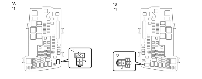
*A for LHD *B for RHD *1 No. 1 Engine Room Relay Block and Junction Block Assembly *2 EFI-MAIN NO. 3 Relay -
Measure the voltage according to the value(s) in the table below.
Standard Voltage Tester Connection Condition Specified Condition 3 (EFI-MAIN NO. 3 relay) - Body ground Always 11 to 14 V Result Proceed to OK NG
NG
REPAIR OR REPLACE HARNESS OR CONNECTOR (BATTERY - EFI-MAIN NO. 3 RELAY)
OK
-
-
CHECK HARNESS AND CONNECTOR (EFI-MAIN NO. 3 RELAY - BODY GROUND)
-
Remove the EFI-MAIN NO. 3 relay from the No. 1 engine room relay block and junction block assembly.
-
Measure the resistance according to the value(s) in the table below.
Standard Resistance Tester Connection Condition Specified Condition 1 (EFI-MAIN NO. 3 relay) - Body ground Always Below 1 Ω Result Proceed to OK NG
NG
REPAIR OR REPLACE HARNESS OR CONNECTOR
OK
-
-
CHECK HARNESS AND CONNECTOR (EFI-MAIN NO. 3 RELAY - AIR BY-PASS VALVE ASSEMBLY)
-
Remove the EFI-MAIN NO. 3 relay, A/F HTR relay, VVT NO. 1 relay and VVT NO. 2 relay from the No. 1 engine room relay block and junction block assembly.
Tech Tips
Remove the A/F HTR relay, VVT NO. 1 relay and VVT NO. 2 relay connected between the checked terminals as the coil inside the relay influences the measurement value.
-
Disconnect the air by-pass valve assembly connector.
-
Measure the resistance according to the value(s) in the table below.
Standard Resistance Tester Connection Condition Specified Condition 5 (EFI-MAIN NO. 3 relay) - D36-1 (+B) Always Below 1 Ω 5 (EFI-MAIN NO. 3 relay) - D38-1 (+B) Always Below 1 Ω 5 (EFI-MAIN NO. 3 relay) or D36-1 (+B) - Body ground and other terminals Always 10 kΩ or higher 5 (EFI-MAIN NO. 3 relay) or D38-1 (+B) - Body ground and other terminals Always 10 kΩ or higher Result Proceed to OK NG
OK
REPAIR OR REPLACE HARNESS OR CONNECTOR (EFI-MAIN NO. 1 RELAY - EFI-MAIN NO. 3 RELAY)
NG
REPAIR OR REPLACE HARNESS OR CONNECTOR
-
-
CLEAR DTC
-
Connect the GTS to the DLC3.
-
Turn the engine switch on (IG).
-
Turn the GTS on.
-
Clear the DTCs.
Powertrain > Engine > Clear DTCs -
Turn the engine switch off and wait for at least 30 seconds.
Result Proceed to NEXT
NEXT
-
-
READ OUTPUT DTC
-
Start the engine and warm it up until the engine coolant temperature reaches 75°C (167°F) or higher.
-
Turn the engine switch off and wait for at least 30 seconds.
-
Start the engine and wait 1 minute or more.
Tech Tips
At this time, waste gate valve and air by-pass valve active detection is performed to check for malfunctions in the waste gate valve and air by-pass valve system.
-
Turn the GTS on.
-
Enter the following menus: Powertrain / Engine / Trouble Codes.
-
Read the DTCs.
Powertrain > Engine > Trouble CodesResult Result Proceed to DTC is not output A DTCs are output B
B
GO TO DTC CHART Click here
A
-
-
CHECK INTAKE SYSTEM (AIR SUCTION)
-
Check that there is no air suction from each part of the intake system while idling (disconnected vacuum hoses, vacuum suction from gaskets).
OK No air suction. Tech Tips
Perform "Inspection After Repair" after repairing or replacing the intake system.
Result Proceed to OK NG
NG
REPAIR OR REPLACE INTAKE SYSTEM
OK
-
-
CHECK INTAKE SYSTEM
-
Check that there is no blockage in the intake system.
Tech Tips
-
If there is a difference in the values for the Data List items "Boost Pressure Sensor" and "Boost Pressure Sensor2" only in the boost range, the turbocharger may be the cause of the malfunction.
-
Comparing the output values for the Data List items "MAF Sensor Bank1", "MAF Sensor Bank2", "Boost Pressure Sensor" and "Boost Pressure Sensor2" can be useful when troubleshooting.
-
If there is no foreign matter in the intake system components, check the mass air flow meter sub-assembly and remove any foreign matter. If the foreign matter cannot be removed, replace the mass air flow meter sub-assembly.
-
Perform "Inspection After Repair" after repairing or replacing the intake system.
-
-
Check the air cleaner filter element sub-assembly.
Tech Tips
If there is any dirt or clogging in the air cleaner filter element sub-assembly, clean or replace it.
Result Proceed to OK NG
NG
REPAIR OR REPLACE INTAKE SYSTEM
OK
-
-
CHECK EXHAUST SYSTEM
-
Check for clogging in the exhaust system.
Tech Tips
-
Clogging in the exhaust system can cause a catalyst erosion or clogging. Therefore, remove the exhaust system by performing a visual check.
-
Perform "Inspection After Repair" after repairing or replacing the exhaust system.
Result Proceed to OK NG -
NG
REPAIR OR REPLACE EXHAUST SYSTEM
OK
-
-
CHECK WHETHER DTC OUTPUT RECURS (P23AA72 AND/OR P2C2972)
-
Connect the GTS to the DLC3.
-
Start the engine.
-
Turn the GTS on.
-
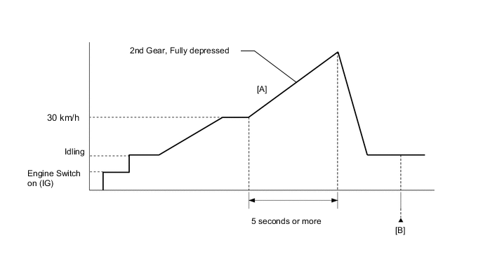
Accelerate up to 30 km/h, change the shift position to 2nd gear and then drive for 5 seconds or more with the accelerator pedal completely depressed [A].
CAUTION:
When performing the confirmation driving pattern, obey all speed limits and traffic laws.
-
Enter the following menus: Powertrain / Engine / Trouble Codes [B].
-
Read the DTCs.
Powertrain > Engine > Trouble CodesResult Proceed to NEXT
NEXT
END
-