SFI SYSTEM(w/o Canister Pump Module), Diagnostic DTC:P023400
| DTC Code | DTC Name |
|---|---|
| P023400 | Turbocharger/Supercharger "A" Overboost Condition |
DESCRIPTION
Refer to DTC P003312.
| DTC No. | Detection Item | DTC Detection Condition | Trouble Area | MIL | Memory | Note |
|---|---|---|---|---|---|---|
| P023400 | Turbocharger/Supercharger "A" Overboost Condition | Either of the following conditions is met (1 trip detection logic).
|
|
- | DTC stored | SAE: P0234 |
MONITOR DESCRIPTION
If the boost pressure exceeds the threshold value (calculated from turbocharger speed upper limit value or compressor downstream temperature upper limit value), there may be a turbocharger system malfunction. In this case, the ECM stores a DTC.
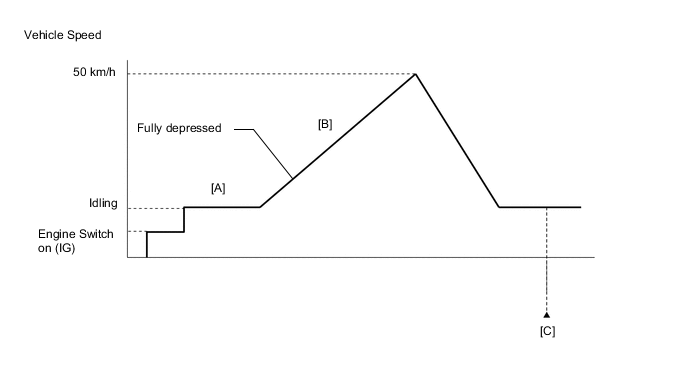
CONFIRMATION DRIVING PATTERN
-
Connect the GTS to the DLC3.
-
Turn the engine switch on (IG) and turn the GTS on.
-
Clear the DTCs (even if no DTCs are stored, perform the clear DTC procedure).
-
Turn the engine switch off and wait for at least 30 seconds.
-
Turn the engine switch on (IG) and turn the GTS on.
-
Start the engine and warm it up until the engine coolant temperature reaches 75°C (167°F) or higher [A].
-
Accelerate to 50 km/h (31 mph) or more with the accelerator pedal fully depressed [B].
CAUTION:
When performing the confirmation driving pattern, obey all speed limits and traffic laws.
-
Enter the following menus: Powertrain / Engine / Trouble Codes [C].
-
Read the pending DTCs.
Tech Tips
-
If a pending DTC is output, the system is malfunctioning.
-
If a pending DTC is not output, perform the following procedure.
-
-
Enter the following menus: Powertrain / Engine / Utility / All Readiness.
-
Input the DTC: P023400.
-
Check the DTC judgment result.
GTS Display Description NORMAL
-
DTC judgment completed
-
System normal
ABNORMAL
-
DTC judgment completed
-
System abnormal
INCOMPLETE
-
DTC judgment not completed
-
Perform driving pattern after confirming DTC enabling conditions
N/A
-
Unable to perform DTC judgment
-
Number of DTCs which do not fulfill DTC preconditions has reached ECU memory limit
Tech Tips
-
If the judgment result shows NORMAL, the system is normal.
-
If the judgment result shows ABNORMAL, the system has a malfunction.
-
If the judgment result shows INCOMPLETE or N/A, perform steps [B] and [C] again.
-
WIRING DIAGRAM
Refer to DTC P010012 for the mass air flow meter sub-assembly circuit.
Refer to DTC P011011 for intake air temperature sensor (built into mass air flow meter sub-assembly) circuit.
Refer to DTC P023511 for No. 2 turbo pressure sensor circuit.
Refer to DTC P024313 for vacuum regulating valve assembly circuit.
CAUTION / NOTICE / HINT
Tech Tips
Read freeze frame data using the GTS. The ECM records vehicle and driving condition information as freeze frame data the moment a DTC is stored. When troubleshooting, freeze frame data can help determine if the vehicle was moving or stationary, if the engine was warmed up or not, if the air fuel ratio was lean or rich, and other data from the time the malfunction occurred.
PROCEDURE
-
CHECK ANY OTHER DTCS OUTPUT (IN ADDITION TO DTC P023400)
-
Connect the GTS to the DLC3.
-
Turn the engine switch on (IG).
-
Turn the GTS on.
-
Enter the following menus: Powertrain / Engine / Trouble Codes.
-
Read the DTCs.
Powertrain > Engine > Trouble CodesResult Result Proceed to DTC P023400 is output A DTC P023400 and other DTCs are output B Tech Tips
If any DTCs other than P023400 are output, troubleshoot those DTCs first.
B 
GO TO DTC CHART Click here
A 
-
-
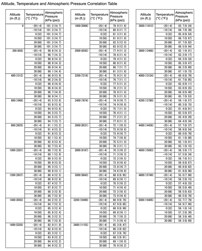
READ VALUE USING GTS (ATMOSPHERIC PRESSURE)
-
Connect the GTS to the DLC3.
-
Turn the engine switch on (IG).
-
Enter the following menus: Powertrain / Engine / Data List / Atmospheric Pressure.
Powertrain > Engine > Data ListTester Display Atmospheric Pressure -
Using the table, read the normal atmospheric pressure value for the applicable altitude and temperature.
Tech Tips
-
Standard atmospheric pressure is approximately 101 kPa(abs) (15 psi(abs)).
-
For every 100 m (328 ft.) increase in altitude, atmospheric pressure drops by approximately 1 kPa (0.15 psi). This varies by weather.
-
-
Compare the Atmospheric pressure value in the Data List with the normal atmospheric value from the table.
Result Result Proceed to Other than the following A Difference between Atmospheric Pressure in the Data List and normal atmospheric pressure value is 10 kPa (1.45 psi) or more. B
B
REPLACE ECM Click here
A
-
-
READ VALUE USING GTS (INTAKE AIR TEMPERATURE)
-
Connect the GTS to the DLC3.
-
Turn the engine switch on (IG).
-
Turn the GTS on.
-
Enter the following menus: Powertrain / Engine / Data List / Intake Air Temperature.
Powertrain > Engine > Data ListTester Display Intake Air Temperature -
Read the value displayed on the GTS.
Result Result Proceed to Difference between Intake Air Temperature in the Data List and actual outside air temperature value is 10°C (18°F) or more. A Other than above B
B 
INSPECT MASS AIR FLOW METER SUB-ASSEMBLY (INTAKE AIR TEMPERATURE SENSOR) Click here
A
-
-
INSPECT MASS AIR FLOW METER SUB-ASSEMBLY
-
Inspect the mass air flow meter sub-assembly, referring to the On-vehicle Inspection for Mass Air Flow Meter.
-
Inspect the mass air flow meter sub-assembly, referring to the Inspection for Mass Air Flow Meter.
-
Inspect the function of the mass air flow meter sub-assembly.
-
Connect the GTS to the DLC3.
-
Start the engine.
-
Turn the GTS on.
-
Allow the engine to idle until Coolant Temperature reaches 75°C (167°F) or higher.
-
Enter the following menus: Powertrain / Engine / Data List / Mass Air Flow Sensor.
Powertrain > Engine > Data ListTester Display Mass Air Flow Sensor -
Read Mass Air Flow Sensor with the engine speed at 3000 rpm.
Standard GTS Display Condition Specified Condition Mass Air Flow Sensor Shift lever position: N
A/C: Off
Engine Speed: 3000 rpm
Between 6.0 gm/sec and 18.0 gm/sec
Result Proceed to OK NG -
NG
CHECK TERMINAL VOLTAGE (POWER SOURCE OF MASS AIR FLOW METER SUB-ASSEMBLY) Click here
OK
-
-
INSPECT NO. 2 TURBO PRESSURE SENSOR
-
Inspect the No. 2 turbo pressure sensor.
Result Proceed to OK NG
NG
CHECK TERMINAL VOLTAGE (POWER SOURCE OF NO. 2 TURBO PRESSURE SENSOR) Click here
OK
-
-
INSPECT WASTE GATE VALVE (TURBINE WITH VALVE HOUSING SUB-ASSEMBLY)
-
Inspect the waste gate valve.
Result Proceed to OK NG
NG
REPLACE TURBINE WITH VALVE HOUSING SUB-ASSEMBLY Click here
OK
-
-
INSPECT VACUUM REGULATING VALVE ASSEMBLY
-
Inspect the vacuum regulating valve assembly.
Result Proceed to OK NG
NG
REPLACE VACUUM REGULATING VALVE ASSEMBLY Click here
OK
-
-
INSPECT WASTE GATE VALVE ACTUATOR WITH BRACKET ASSEMBLY
-
Inspect the waste gate valve actuator with bracket assembly.
Result Proceed to OK NG
NG
REPLACE WASTE GATE VALVE ACTUATOR WITH BRACKET ASSEMBLY Click here
OK
-
-
CHECK HARNESS AND CONNECTOR (VACUUM REGULATING VALVE ASSEMBLY - ECM)
-
Disconnect the vacuum regulating valve assembly connector.
-
Disconnect the ECM connector.
-
Measure the resistance according to the value(s) in the table below.
Standard Resistance Tester Connection Condition Specified Condition C23-1 (+) - C20-37 (WGV+) Always Below 1 Ω C23-2 (-) - C20-36 (WGV-) Always Below 1 Ω C23-1 (+) or C20-37 (WGV+) - Body ground and other terminals Always 10 kΩ or higher C23-2 (-) or C20-36 (WGV-) - Body ground and other terminals Always 10 kΩ or higher Result Proceed to OK NG
NG
REPAIR OR REPLACE HARNESS OR CONNECTOR
OK
-
-
CHECK WHETHER DTC OUTPUT RECURS (DTC P023400)
-
Connect the GTS to the DLC3.
-
Turn the engine switch on (IG).
-
Turn the GTS on.
-
Clear the DTCs.
Powertrain > Engine > Clear DTCs -
Turn the engine switch off and wait for at least 30 seconds.
-
Start the engine and warm it up.
-
Turn the GTS on.
-
Drive the vehicle in accordance with the driving pattern described in Confirmation Driving Pattern.
-
Enter the following menus: Powertrain / Engine / Utility / All Readiness.
Powertrain > Engine > UtilityTester Display All Readiness -
Input the DTC: P023400.
-
Check the DTC judgment result.
Result Result Proceed to NORMAL
(DTCs are not output)
A ABNORMAL
(DTC P023400 is output)
B
A
END
B
REPLACE ECM Click here
-
-
CHECK TERMINAL VOLTAGE (POWER SOURCE OF NO. 2 TURBO PRESSURE SENSOR)
-
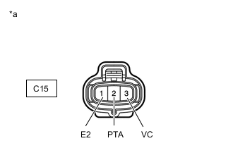
*a Front view of wire harness connector
(to No. 2 Turbo Pressure Sensor)
Disconnect the No. 2 turbo pressure sensor connector.
-
Turn the engine switch on (IG).
-
Measure the voltage according to the value(s) in the table below.
Standard Voltage Tester Connection Condition Specified Condition C15-3 (VC) - C15-1 (E2) Engine switch on (IG) 4.5 to 5.5 V C15-2 (PTA) - C15-1 (E2) Engine switch on (IG) 3.0 to 5.5 V Result Proceed to OK NG
OK
REPLACE NO. 2 TURBO PRESSURE SENSOR Click here
NG
-
-
CHECK HARNESS AND CONNECTOR (NO. 2 TURBO PRESSURE SENSOR - ECM)
-
Disconnect the No. 2 turbo pressure sensor connector.
-
Disconnect the ECM connector.
-
Measure the resistance according to the value(s) in the table below.
Standard Resistance Tester Connection Condition Specified Condition C15-3 (VC) - C20-140 (VPTA) Always Below 1 Ω C15-1 (E2) - C20-139 (EPTA) Always Below 1 Ω C15-2 (PTA) - C20-108 (PTA) Always Below 1 Ω C15-3 (VC) or C20-140 (VPTA) - Body ground and other terminals Always 10 kΩ or higher C15-2 (PTA) or C20-108 (PTA) - Body ground and other terminals Always 10 kΩ or higher Result Proceed to OK NG
OK
REPLACE ECM Click here
NG
REPAIR OR REPLACE HARNESS OR CONNECTOR
-
-
CHECK TERMINAL VOLTAGE (POWER SOURCE OF MASS AIR FLOW METER SUB-ASSEMBLY)
-
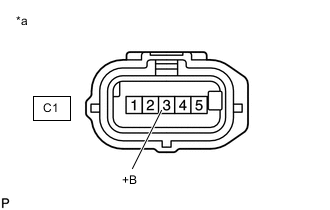
*a Front view of wire harness connector
(to Mass Air Flow Meter Sub-assembly)
Disconnect the mass air flow meter sub-assembly connector.
-
Turn the engine switch on (IG).
-
Measure the voltage according to the value(s) in the table below.
Standard Voltage Tester Connection Switch Condition Specified Condition C1-3 (+B) - Body ground Engine switch on (IG) 11 to 14 V Result Proceed to OK NG
NG
REPAIR OR REPLACE HARNESS OR CONNECTOR (MASS AIR FLOW METER SUB-ASSEMBLY - EFI-MAIN NO. 1 RELAY)
OK
-
-
CHECK HARNESS AND CONNECTOR (MASS AIR FLOW METER SUB-ASSEMBLY - ECM)
-
Disconnect the mass air flow meter sub-assembly connector.
-
Disconnect the ECM connector.
-
Measure the resistance according to the value(s) in the table below.
Standard Resistance Tester Connection Condition Specified Condition C1-5 (VG) - C20-92 (VG) Always Below 1 Ω C1-4 (E2G) - C20-91 (E2G) Always Below 1 Ω C1-5 (VG) or C20-92 (VG) - Body ground and other terminals Always 10 kΩ or higher Tech Tips
Perform "Inspection After Repair" after replacing the mass air flow meter sub-assembly.
Result Proceed to OK NG
OK
REPLACE MASS AIR FLOW METER SUB-ASSEMBLY Click here
NG
REPAIR OR REPLACE HARNESS OR CONNECTOR
-
-
INSPECT MASS AIR FLOW METER SUB-ASSEMBLY (INTAKE AIR TEMPERATURE SENSOR)
-
Inspect the mass air flow meter sub-assembly (intake air temperature sensor).
Tech Tips
Perform "Inspection After Repair" after replacing the mass air flow meter sub-assembly.
Result Proceed to OK NG
NG
REPLACE MASS AIR FLOW METER SUB-ASSEMBLY Click here
OK
-
-
CHECK HARNESS AND CONNECTOR (MASS AIR FLOW METER SUB-ASSEMBLY - ECM)
-
Disconnect the mass air flow meter sub-assembly connector.
-
Disconnect the ECM connector.
-
Measure the resistance according to the value(s) in the table below.
Standard Resistance Tester Connection Condition Specified Condition C1-1 (THA) - C20-94 (THA) Always Below 1 Ω C1-2 (E2) - C20-93 (ETHA) Always Below 1 Ω C1-1 (THA) or C20-94 (THA) - Body ground and other terminals Always 10 kΩ or higher Result Proceed to OK NG
OK
REPLACE ECM Click here
NG
REPAIR OR REPLACE HARNESS OR CONNECTOR
-