OIL PUMP REMOVAL

-
DISCHARGE FUEL SYSTEM PRESSURE
-
PRECAUTION
Note
After turning the ignition switch off, waiting time may be required before disconnecting the cable from the battery terminal. Therefore, make sure to read the disconnecting the cable from the battery terminal notice before proceeding with work Click here.
-
DISCONNECT CABLE FROM NEGATIVE BATTERY TERMINAL
Note
When disconnecting the cable, some systems need to be initialized after the cable is reconnected Click here.
-
REMOVE FAN AND GENERATOR V BELT
-
DRAIN ENGINE COOLANT
CAUTION:
Do not remove the radiator reservoir cap sub-assembly while the engine and radiator are still hot. Pressurized, hot engine coolant and steam may be released and cause serious burns.
Tech Tips
Collect the engine coolant in a container and dispose of it according to the local regulations.
-
Loosen the radiator drain cock plug and drain the engine coolant.
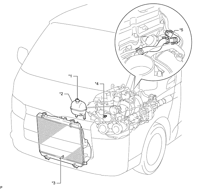
Text in Illustration *1 Radiator Reservoir Cap Sub-assembly *2 Radiator Reservoir Assembly *3 Radiator Drain Cock Plug *4 Cylinder Block Water Drain Cock Plug *5 2-Way - - -
Remove the radiator reservoir cap sub-assembly.
-
Loosen the cylinder block water drain cock plug and drain the engine coolant from the engine.
-
-
DRAIN ENGINE OIL
-
Remove the oil filler cap.
-
Remove the oil pan drain plug and gasket, and then drain the engine oil into a container.
Note
Collect the oil in a disposable oil container.
-
Clean the oil pan drain plug and install it with a new gasket.
- Torque:
- 38 N*m { 382 kgf*cm, 28 ft.*lbf }
-
-
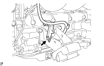
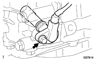
REMOVE CAMSHAFT POSITION SENSOR
-
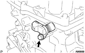
Disconnect the camshaft position sensor connector.
-
Remove the bolt and camshaft position sensor.
-
-
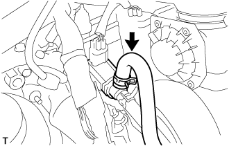
DISCONNECT NO. 2 RADIATOR HOSE
-
Slide the clamp and disconnect the No. 2 radiator hose from the No. 1 radiator pipe.
-
-
DISCONNECT NO. 4 RADIATOR HOSE
-
Slide the clamp and disconnect the No. 4 radiator hose from the engine.
-
-
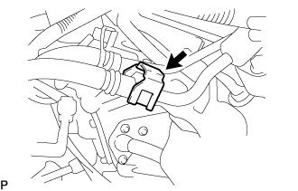
DISCONNECT FUEL VAPOR FEED HOSE ASSEMBLY
-
Slide the clamp and disconnect the fuel vapor feed hose from the purge VSV.
-
-
DISCONNECT UNION TO CONNECTOR TUBE HOSE
-
Slide the clamp and disconnect the union to connector tube hose from the intake manifold.
-
-
REMOVE INTAKE AIR CONNECTOR
-
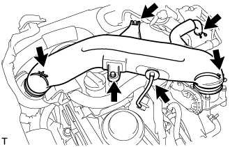
Slide the clamp and disconnect the No. 2 PCV hose from the cylinder head cover sub-assembly.
-
Disconnect the vacuum hose from the intake air connector.
-
Loosen the 2 hose clamps.
-
Remove the 2 bolts and intake air connector.
-
-
DISCONNECT NO. 1 FUEL HOSE
-
Disconnect the No. 1 fuel hose from the fuel pressure pulsation damper assembly Click here.
-
-
DISCONNECT NO. 2 FUEL HOSE
-
Disconnect the No. 2 fuel hose from the fuel delivery pipe sub-assembly Click here.
-
-
DISCONNECT VANE PUMP ASSEMBLY
-
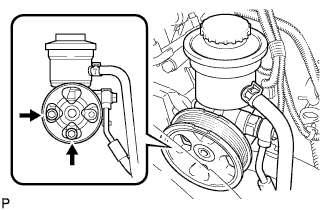
Disconnect the oil pressure switch connector.
-
Remove the 2 bolts and disconnect the vane pump assembly from the engine.
-
Support the vane pump assembly securely.
-
-
REMOVE ENGINE OIL LEVEL DIPSTICK
-
REMOVE ENGINE OIL LEVEL DIPSTICK GUIDE
-
Remove the bolt, engine oil level dipstick guide and O-ring.
-
-
DISCONNECT COMPRESSOR AND MAGNETIC CLUTCH
-
Disconnect the compressor and magnetic clutch connector.
-
Remove the 4 bolts and disconnect the compressor and magnetic clutch from the engine.
Tech Tips
Disconnect the compressor and magnetic clutch with the No. 1 cooler refrigerant suction hose and No. 1 cooler refrigerant discharge hose stuck by suspended from the rope.
-
Support the compressor and magnetic clutch securely.
-
-
DISCONNECT ENGINE WIRE
-
Disconnect the wire harness support of the ECM.
-
Disconnect the connectors of the ECM.
-
Disconnect the clamps of the engine wire and ground cable.
-
Disconnect the starter connector Click here.
-
Disconnect the generator connector Click here.
-
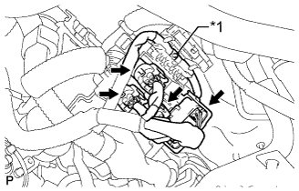
Text in Illustration *1 Nut Remove the nut and disconnect the 4 connectors from the engine room junction block.
-
-
REMOVE THROTTLE WITH MOTOR BODY ASSEMBLY
-
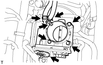
Disconnect the throttle motor connector.
-
Slide the clamp and disconnect the water by-pass hose from the throttle body.
-
Slide the clamp and disconnect the No. 2 water by-pass hose from the throttle body.
-
Remove the 4 bolts and throttle body assembly.
-
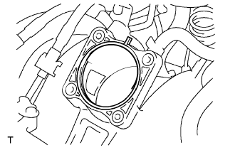
Remove the gasket from the intake manifold.
-
-
REMOVE FUEL DELIVERY PIPE SUB-ASSEMBLY
Note
Be careful not to drop the fuel injector assemblies when removing the fuel delivery pipe sub-assembly.
-
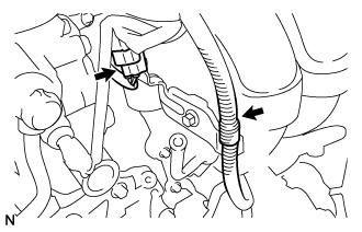
Disconnect the vacuum hose from the fuel pressure regulator assembly.
-
Slide the clamp and disconnect the No. 2 fuel hose from the fuel pressure regulator assembly.
-
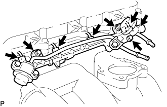
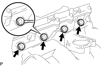
Disconnect the 4 fuel injector connectors.
-
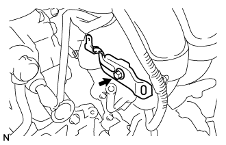
Remove the 2 bolts, fuel pressure pulsation damper assembly and O-ring.
-
Remove the 2 bolts and fuel delivery pipe sub-assembly together with the 4 fuel injector assemblies.
Note
Be careful not to drop the fuel injector assemblies when removing the fuel delivery pipe sub-assembly.
-
Remove the 2 No. 1 delivery pipe spacers from the cylinder head sub-assembly.
-
Remove the 4 injector vibration insulators.
-
Using a screwdriver, pry out the 4 injector spacers and 4 O-rings from the cylinder head sub-assembly.
-
-
REMOVE INJECTOR ASSEMBLY
-
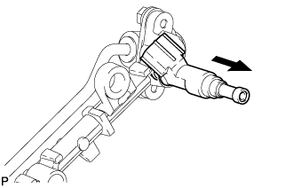
Pull out the 4 fuel injector assemblies from the fuel delivery pipe sub-assembly.
Text in Illustration 
Pull Out -
Remove the O-rings from the fuel injector assemblies.
-
-
REMOVE INTAKE MANIFOLD
-
Disconnect the vacuum switching valve connector.
-
Slide the clamp and disconnect the purge line hose from the vacuum switching valve.
-
Detach the 2 wire harness clamps from the wire harness bracket.
-
Slide the clamp and disconnect the No. 3 PCV hose from the intake manifold.
-
Slide the clamp and disconnect the vacuum hose from the intake manifold.
-
Remove the bolt and wire harness bracket from the intake manifold.
-
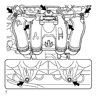
Remove the 5 bolts, 2 nuts and intake manifold.
-
Remove the gasket from the intake manifold.
-
-
REMOVE FAN PULLEY
-
Remove the 4 nuts, fan pulley and fan spacer.
-
-
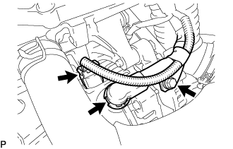
REMOVE NO. 1 WATER BY-PASS PIPE
-
Remove the bolt, 2 nuts, water by-pass pipe and gasket.
-
-
REMOVE WATER INLET
-
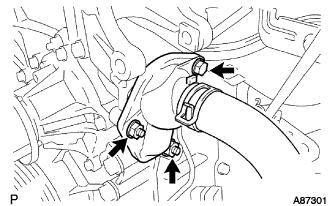
Remove the 2 nuts and bolt and disconnect the water inlet.
-
Remove the gasket.
-
-
REMOVE THERMOSTAT
-
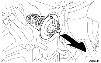
Remove the thermostat and gasket.
-
-
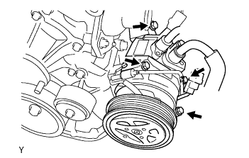
REMOVE GENERATOR ASSEMBLY
-
Disconnect the generator connector.
-
Remove the terminal cap.
-
Remove the nut and disconnect the wire harness from terminal B.
-
Remove the bolt and disconnect the wire harness clamp.
-
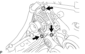
Remove the 3 bolts and generator assembly.
-
-
REMOVE NO. 1 COMPRESSOR MOUNTING BRACKET
-
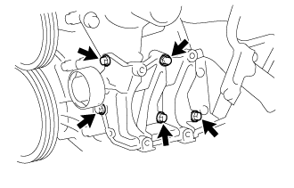
Remove the 5 bolts and No. 1 compressor mounting bracket.
-
-
REMOVE NO. 1 IDLER PULLEY SUB-ASSEMBLY
-
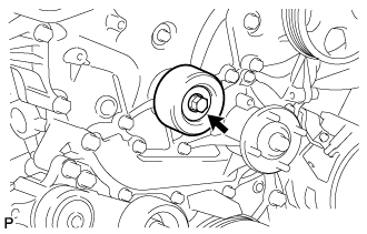
Remove the bolt, pulley plate, collar and No. 1 idler pulley sub-assembly.
-
-
REMOVE V-RIBBED BELT TENSIONER ASSEMBLY
-
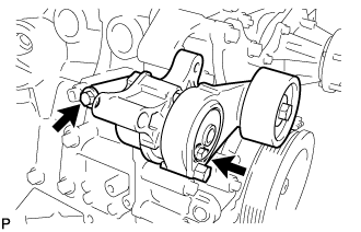
Remove the 2 bolts and V-ribbed belt tensioner assembly.
-
-
REMOVE IGNITION COIL ASSEMBLY
-
Remove the 4 bolts and 4 ignition coil assemblies.
-
-
REMOVE CYLINDER HEAD COVER SUB-ASSEMBLY
-
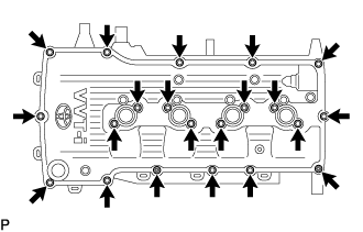
Remove the 19 bolts, 2 nuts and cylinder head cover sub-assembly.
-
Remove the cylinder head cover gasket and No. 2 cylinder head cover gasket from the cylinder head cover sub-assembly.
-
-
REMOVE CRANKSHAFT POSITION SENSOR
-
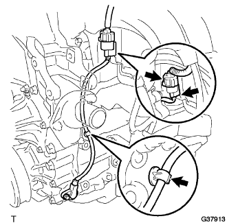
Disconnect the crankshaft position sensor connector and detach the 2 wire harness clamps.
-
Remove the bolt and crankshaft position sensor.
-
-
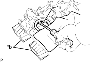
REMOVE CRANKSHAFT PULLEY
-
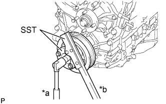
Text in Illustration *a Loosen *b Hold Using SST, hold the crankshaft pulley and loosen the pulley bolt until 2 or 3 threads are screwed into the crankshaft.
- SST
- 09213-54015 ( 91651-60855 )
- 09330-00021
-
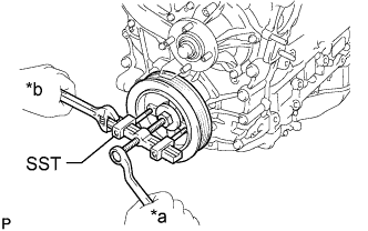
Text in Illustration *a Turn *b Hold Using SST and the pulley bolt, remove the crankshaft pulley and pulley bolt.
- SST
- 09950-50013 ( 09951-05010, 09952-05010, 09953-05010, 09954-05021 )
Tech Tips
Apply lubricant to the threads and end of SST.
-
-
REMOVE NO. 2 OIL PAN SUB-ASSEMBLY
-
Remove the oil pan drain plug and gasket.
-
Remove the 18 bolts and 2 nuts.
-
Insert the blade of an oil pan seal cutter between the oil pans. Cut through the applied sealer and remove the No. 2 oil pan sub-assembly.
Note
Do not damage the contact surfaces of the oil pans.
-
-
REMOVE OIL STRAINER SUB-ASSEMBLY
-
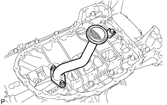
Remove the bolt, 2 nuts, oil strainer sub-assembly and gasket.
-
-
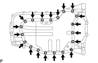
REMOVE OIL PAN SUB-ASSEMBLY
-
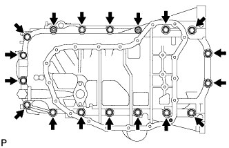
Remove the 16 bolts and 2 nuts.
-
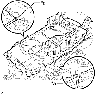
Text in Illustration *a Protective Tape Remove the oil pan sub-assembly by prying between the oil pan sub-assembly and cylinder block with a screwdriver.
Note
Do not damage the contact surfaces of the cylinder block and oil pan sub-assembly.
Tech Tips
Tape the screwdriver tip before use.
-
Remove the O-ring.
-
-
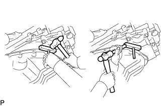
REMOVE TIMING CHAIN OR BELT COVER SUB-ASSEMBLY
-
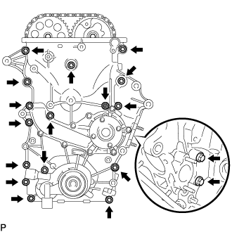
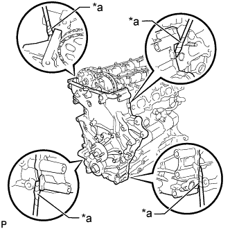
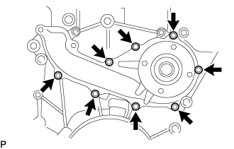
Remove the 17 bolts and nut shown in the illustration.
-
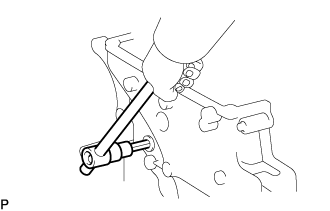
Text in Illustration *a Protective Tape Remove the timing chain or belt cover sub-assembly by prying between the timing chain or belt cover sub-assembly and cylinder head sub-assembly or cylinder block sub-assembly with a screwdriver.
Note
Do not damage the contact surfaces of the cylinder head sub-assembly, cylinder block sub-assembly and timing chain or belt cover sub-assembly.
Tech Tips
Tape the screwdriver tip before use.
-
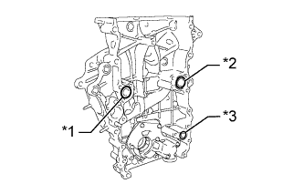
Text in Illustration *1 Timing Chain Cover O-ring *2 Water Pump O-ring *3 Oil Pump O-ring Remove the 3 O-rings from the timing chain or belt cover sub-assembly.
-
Using a 10 mm socket hexagon wrench, remove the timing chain cover plug from the timing chain or belt cover sub-assembly.
-
-
REMOVE ENGINE WATER PUMP ASSEMBLY
-
Remove the 8 bolts, engine water pump assembly and gasket from the timing chain or belt cover sub-assembly.
-
-
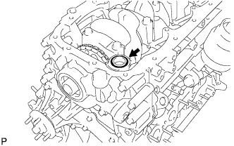
REMOVE TIMING CHAIN CASE OIL SEAL
-
Text in Illustration *a Protective Tape *b Wooden Block Using a screwdriver, pry out the timing chain case oil seal from the timing chain or belt cover sub-assembly.
Tech Tips
Tape the screwdriver tip before use.
-
-
REMOVE OIL PUMP RELIEF VALVE
-
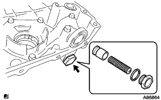
Using a 27 mm socket wrench, remove the plug and gasket.
-
Remove the relief valve spring and oil pump relief valve from the timing chain or belt cover sub-assembly.
-