ENGINE ASSEMBLY INSTALLATION
PROCEDURE
INSTALL ENGINE HANGER
REMOVE ENGINE STAND
-
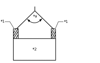
*1
Engine Hanger
*2
Engine Assembly
*a
50° or less
Attach an engine sling device and hang the engine assembly with a chain block.
Note:When hanging the engine assembly, make sure to hang the engine assembly with the angle of the sling device at 50° or less. If not, the engine assembly or engine hangers may be damaged.
Lift the engine assembly and remove it from the engine stand.
Note:With the exception of installing the engine assembly to an engine stand or removing the engine assembly from an engine stand, do not perform any work on the engine while it is suspended, as doing so is dangerous.
Pay attention to the angle of the sling device as the engine assembly or engine hangers may be damaged or deformed if the angle is incorrect.
Place the engine assembly onto a workbench.
-
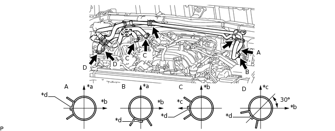
INSTALL NO. 1 WATER BY-PASS PIPE
-
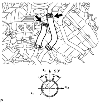
*a
Upper Side
*b
RH Side
*c
Paint Mark
Connect the 2 water by-pass hoses to the No. 4 water by-pass pipe and No. 2 water by-pass pipe, and slide the 2 clamps to secure the hoses and install the No. 1 water by-pass pipe.
Tip:When connecting the water by-pass hoses, make sure the paint marks and clamps are as shown in the illustration.
The direction of the hose clamp is indicated in the illustration.
-
INSTALL ENGINE ASSEMBLY
Attach an engine sling device and hang the engine assembly with a chain block.
Slowly lower the engine assembly into the engine compartment.
-

Bolt

Nut
Install the front engine mounting insulator LH and RH with the 2 nuts and 4 bolts.
for nut
72 N*m
734 kgf*cm
53 ft.*lbf
for bolt
57 N*m
581 kgf*cm
42 ft.*lbf
Remove the 2 bolts and 2 engine hangers.
INSTALL DRIVE PLATE AND RING GEAR SUB-ASSEMBLY
Using SST, hold the crankshaft.
09213-70011
09213-70020
09330-00021
-
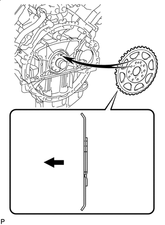
Engine Side
Install the crankshaft angle sensor rotor.
Tip:Align the pin hole of the crankshaft angle sensor rotor with the pin of the crankshaft.
As the crankshaft angle sensor rotor is not reversible, be sure to install it so that it is facing in the direction shown in the illustration.
-
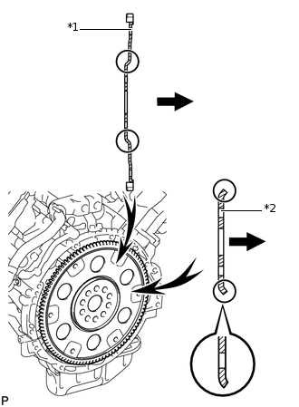
*1
Drive Plate and Ring Gear Sub-assembly
*2
Rear Drive Plate Spacer
Transmission Assembly Side
Install the drive plate and ring gear sub-assembly and the rear drive plate spacer to the crankshaft.
Tip:As the rear drive plate spacer and the drive plate and ring gear sub-assembly are not reversible, be sure to install them so that they are facing in the directions shown in the illustration.
Install the drive plate and ring gear sub-assembly and bolts.
Tip:The bolts are tightened in 2 progressive steps.
Clean the bolts and bolt holes.
-
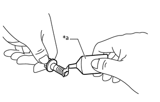
*a
Adhesive
Apply adhesive to 2 or 3 threads at the end of each of the 10 bolts.
Adhesive
Toyota Genuine Adhesive 1324, Three Bond 1324 or equivalent
-
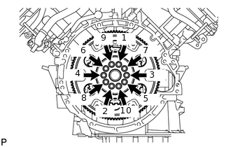
Step 1:
Uniformly install and tighten the 10 new bolts in several steps in the sequence shown in the illustration.
30 N*m
301 kgf*cm
22 ft.*lbf
Mark the top of each drive plate installation bolt with paint.
Step 2:
Tighten the drive plate installation bolts 90°.
Check that the painted marks are now at a 90° angle to the top.
Note:Do not start the engine for at least an hour after installing the drive plate and ring gear sub-assembly.
INSTALL REAR NO. 1 ENGINE MOUNTING INSULATOR
Tip:Perform this procedure only when replacement of the engine mounting insulator is necessary.
Install the rear No. 1 engine mounting insulator to the transfer with the 4 bolts.
72.5 N*m
739 kgf*cm
53 ft.*lbf
Install the rear engine mounting heat insulator to the rear No. 1 engine mounting insulator with the bolt.
12 N*m
122 kgf*cm
9 ft.*lbf
INSTALL AUTOMATIC TRANSMISSION ASSEMBLY
INSTALL DRIVE PLATE AND TORQUE CONVERTER CLUTCH SETTING BOLT
INSTALL PROPELLER SHAFT ASSEMBLY
INSTALL FRONT PROPELLER SHAFT ASSEMBLY
CONNECT OIL COOLER TUBE SUB-ASSEMBLY
Connect the oil cooler tube sub-assembly with the bolt.
14 N*m
143 kgf*cm
10 ft.*lbf
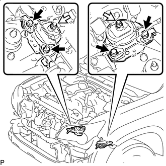
CONNECT ENGINE WIRE
Connect the ECM connector.
Attach the wire harness clamp.
-
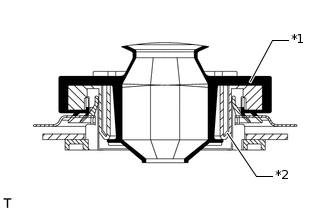
*1
Grommet
*2
Wire Harness Support
Attach the grommet to the wire harness support.
Pass the wire harness into the vehicle and install the wire harness support.
-
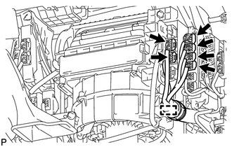
Connect the 6 connectors and attach the clamp.
Install the lower instrument panel.
for Engine Room RH Side:
-
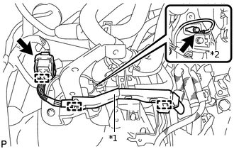
*1
Engine Wire
*2
Ground Wire
Attach the 3 wire harness clamps to connect the engine wire and connect the connector.
Connect the ground wire with the bolt.
8.0 N*m
82 kgf*cm
71 in.*lbf
-
for Engine Room LH Side:
-
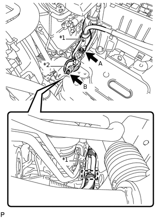
*1
No. 2 Engine Wire
*2
Ground Wire
Attach the wire harness clamp.
Connect the No. 2 engine wire and ground wire with the 2 bolts.
for bolt A
8.0 N*m
82 kgf*cm
71 in.*lbf
for bolt B
19 N*m
194 kgf*cm
14 ft.*lbf
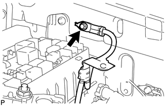
-
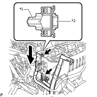
*1
Engine Wire
*2
Engine Room Relay Block
Attach the 2 claws and connect the engine wire to the engine room relay block.
Install the nut to the engine room relay block.
11 N*m
112 kgf*cm
8 ft.*lbf
Connect the connector.
-
Connect the ground wire with the bolt.
8.5 N*m
87 kgf*cm
75 in.*lbf
-
CONNECT FUEL HOSE AND NO. 2 FUEL TUBE SUB-ASSEMBLY
Connect the fuel hose and No. 2 fuel tube sub-assembly.
Attach the clamp and install the fuel pipe clamp to the fuel tube connector.
INSTALL FLYWHEEL HOUSING SIDE COVER
INSTALL STARTER ASSEMBLY
INSTALL STARTER COVER
INSTALL EXHAUST MANIFOLD ASSEMBLY RH
INSTALL NO. 1 EXHAUST MANIFOLD HEAT INSULATOR
INSTALL EXHAUST MANIFOLD ASSEMBLY LH
INSTALL NO. 2 EXHAUST MANIFOLD HEAT INSULATOR
INSTALL NO. 1 EGR PIPE SUB-ASSEMBLY (w/ EGR System)
INSTALL ENGINE OIL LEVEL DIPSTICK GUIDE
INSTALL FRONT EXHAUST PIPE ASSEMBLY
INSTALL FRONT NO. 2 EXHAUST PIPE ASSEMBLY
INSTALL EXHAUST PIPE STOPPER BRACKET
INSTALL COOLER COMPRESSOR ASSEMBLY
INSTALL SUCTION HOSE SUB-ASSEMBLY
Remove the attached vinyl tape from the suction hose sub-assembly.
Sufficiently apply compressor oil to 2 new O-rings and the fitting surface of the cooler compressor.
Compressor oil
ND-OIL 8 or equivalent
Install the 2 O-rings to the suction hose sub-assembly.
-
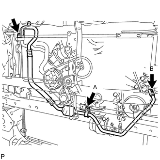
Install the suction hose sub-assembly with the 2 bolts and nut.
for bolt A
7.8 N*m
80 kgf*cm
69 in.*lbf
for bolt B and nut
9.8 N*m
100 kgf*cm
87 in.*lbf
INSTALL DISCHARGE HOSE SUB-ASSEMBLY
Remove the attached vinyl tape from the discharge hose sub-assembly.
Sufficiently apply compressor oil to 2 new O-rings and the fitting surface of the cooler compressor.
Compressor oil
ND-OIL 8 or equivalent
Install the 2 O-rings to the discharge hose sub-assembly.
-
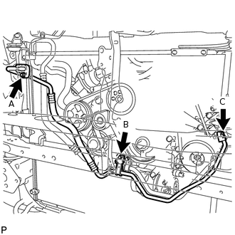
Install the discharge hose sub-assembly with the 3 bolts.
for bolt A
5.4 N*m
55 kgf*cm
48 in.*lbf
for bolt B
7.8 N*m
80 kgf*cm
69 in.*lbf
for bolt C
9.8 N*m
100 kgf*cm
87 in.*lbf
INSTALL GENERATOR ASSEMBLY
INSTALL VANE PUMP ASSEMBLY
CONNECT PRESSURE FEED TUBE
CONNECT NO. 1 OIL RESERVOIR TO PUMP HOSE
INSTALL INTAKE MANIFOLD
INSTALL AIR TUBE SUB-ASSEMBLY
INSTALL VENTILATION HOSE ASSEMBLY
CONNECT NO. 4 WATER BY-PASS PIPE
INSTALL INTAKE FLANGE (w/o EGR System)
Install a new gasket to the intake manifold.
Install the intake flange with the 2 nuts.
10 N*m
102 kgf*cm
7 ft.*lbf
INSTALL EGR VALVE BRACKET
INSTALL NO. 5 WATER BY-PASS PIPE (w/o EGR System)
Install the No. 5 water by-pass pipe with the 2 bolts.
21 N*m
214 kgf*cm
15 ft.*lbf
INSTALL EGR VALVE ASSEMBLY (w/ EGR System)
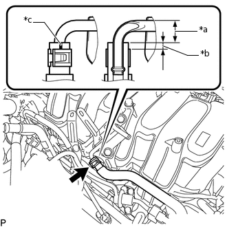
CONNECT NO. 13 WATER BY-PASS HOSE
-
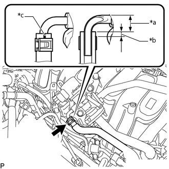
*a
13 to 17 mm (0.512 to 0.669 in.)
*b
5 mm (0.197 in.)
*c
Paint Mark (Blue)
w/ EGR System:
Connect the No. 13 water by-pass hose to the EGR valve sub-assembly, and slide the clamp to secure the hose.
Tip:The direction of the hose clamp is indicated in the illustration.
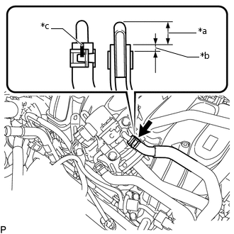
-
*a
13 to 17 mm (0.512 to 0.669 in.)
*b
5 mm (0.197 in.)
*c
Paint Mark (Blue)
w/o EGR System:
Connect the No. 13 water by-pass hose to the No. 5 water by-pass pipe, and slide the clamp to secure the hose.
Tip:The direction of the hose clamp is indicated in the illustration.
-
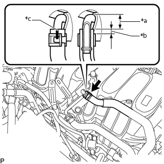
CONNECT NO. 12 WATER BY-PASS HOSE
-
*a
13 to 17 mm (0.512 to 0.669 in.)
*b
5 mm (0.197 in.)
*c
Paint Mark (Green)
w/ EGR System:
Connect the No. 12 water by-pass hose to the EGR valve sub-assembly, and slide the clamp to secure the hose.
Tip:The direction of the hose clamp is indicated in the illustration.
-
*a
13 to 17 mm (0.512 to 0.669 in.)
*b
5 mm (0.197 in.)
*c
Paint Mark (Green)
w/o EGR System:
Connect the No. 12 water by-pass hose to the No. 5 water by-pass pipe, and slide the clamp to secure the hose.
Tip:The direction of the hose clamp is indicated in the illustration.
-
INSTALL WATER PIPE AND HOSE SUB-ASSEMBLY (for Single Air Conditioning System)
*a
Upper Side
*b
LH Side
*c
Rear
*d
Paint Mark
Install the water pipe and hose sub-assembly with the 2 nuts.
9.8 N*m
100 kgf*cm
87 in.*lbf
Connect the 4 water hoses to the water pipe, and slide the 4 clamps to secure the hoses.
Tip:When connecting the water hoses, make sure the paint marks and clamps are as shown in the illustration.
The direction of each hose clamp is indicated in the illustration.
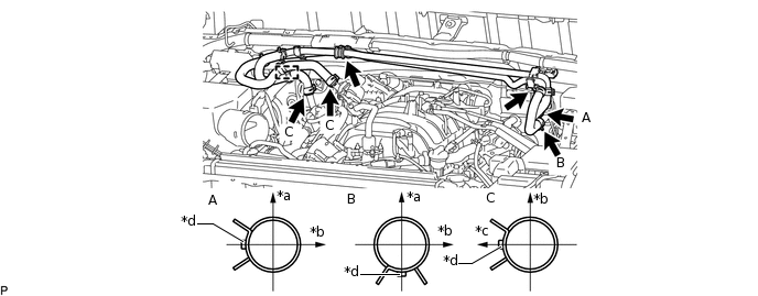
INSTALL WATER PIPE AND HOSE SUB-ASSEMBLY (for Dual Air Conditioning System)
*a
Upper Side
*b
LH Side
*c
Rear
*d
Paint Mark
Install the water pipe and hose sub-assembly with the 2 nuts.
9.8 N*m
100 kgf*cm
87 in.*lbf
Connect the 6 water hoses to the water pipe, and slide the 6 clamps to secure the hoses.
Tip:When connecting the water hoses, make sure the paint marks and clamps are as shown in the illustration.
The direction of each hose clamp is indicated in the illustration.
INSTALL RADIATOR ASSEMBLY
CONNECT OIL COOLER ACCESSORY ASSEMBLY
CONNECT NO. 2 RADIATOR HOSE
INSTALL FAN SHROUD
INSTALL NO. 1 RADIATOR HOSE
INSTALL RADIATOR RESERVOIR ASSEMBLY
INSTALL RADIATOR SIDE DEFLECTOR RH
INSTALL RADIATOR SIDE DEFLECTOR LH
INSTALL AIR CLEANER CASE SUB-ASSEMBLY
Install the air cleaner case sub-assembly with the 3 bolts.
12 N*m
122 kgf*cm
9 ft.*lbf
INSTALL AIR CLEANER FILTER ELEMENT SUB-ASSEMBLY
INSTALL AIR CLEANER CAP AND HOSE
-
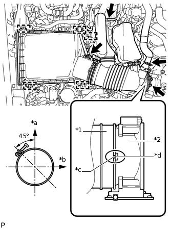
*1
Air Cleaner Hose
*2
Throttle Body Assembly
*a
Upper Side
*b
Front
*c
Groove
*d
Protrusion
Attach the 4 clamps to install the air cleaner cap and hose.
Tip:When installing the air cleaner hose, align its groove with the protrusion of the throttle body assembly as shown in the illustration.
Tighten the hose clamp.
5.0 N*m
51 kgf*cm
44 in.*lbf
Tip:Make sure the direction of the hose clamp is as shown in the illustration.
Connect the mass air flow meter connector and No. 1 air hose and attach the wire harness clamp.
Connect the No. 2 ventilation hose to the air cleaner hose, and slide the clamp the secure the hose.
-
INSTALL FRONT BUMPER COVER
INSTALL BATTERY TRAY
INSTALL BATTERY
Install the battery.
Install the battery hold down clamp with the 2 nuts.
6.0 N*m
61 kgf*cm
53 in.*lbf
Install the No. 2 engine wire with the nut.
7.5 N*m
76 kgf*cm
66 in.*lbf
INSTALL COWL TOP VENTILATOR LOUVER SUB-ASSEMBLY
CONNECT CABLE TO NEGATIVE BATTERY TERMINAL
Note:When disconnecting the cable, some systems need to be initialized after the cable is reconnected.
ADD ENGINE OIL
ADD ENGINE COOLANT
ADD POWER STEERING FLUID
BLEED POWER STEERING FLUID
INSPECT FOR OIL LEAK
INSPECT FOR COOLANT LEAK
INSPECT FOR FUEL LEAK
INSPECT ENGINE OIL LEVEL
INSPECT FOR POWER STEERING FLUID LEAK
INSPECT FOR EXHAUST GAS LEAK
PERFORM RESET MEMORY
INSPECT IGNITION TIMING
INSPECT ENGINE IDLE SPEED
INSPECT CO/HC
INSTALL HOOD SUB-ASSEMBLY
-
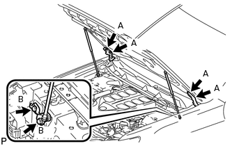
Install the hood sub-assembly with the 8 bolts.
for bolt A
13 N*m
133 kgf*cm
10 ft.*lbf
for bolt B
18 N*m
178 kgf*cm
13 ft.*lbf
Connect the washer hose.
-
ADJUST HOOD SUB-ASSEMBLY
CHARGE REFRIGERANT
WARM UP ENGINE
CHECK FOR REFRIGERANT GAS LEAK
INSTALL ENGINE ROOM SIDE COVER
Install the engine room side cover with the 4 clips.
INSTALL ENGINE ROOM SIDE COVER LH
Install the engine room side cover LH with the 4 clips.
INSTALL V-BANK COVER SUB-ASSEMBLY
-
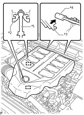
*1
Pin
*2
V-bank Cover Grommet
*3
V-bank Cover Hook
*4
No. 1 V-bank Cover Bracket
Attach the 2 V-bank cover hooks to the No. 1 V-bank cover bracket. Then align the 2 V-bank cover grommets with the 2 pins and press down on the V-bank cover sub-assembly to attach the pins.
-
INSTALL UPPER RADIATOR SUPPORT SEAL
Install the upper radiator support seal with the 14 clips.
INSTALL FRONT NO. 1 FENDER APRON TO FRAME SEAL RH
Install the front No. 1 fender apron to frame seal RH with the 5 clips.
INSTALL FRONT NO. 1 FENDER APRON TO FRAME SEAL LH
Install the front No. 1 fender apron to frame seal LH with the 5 clips.
INSTALL FRONT FENDER APRON SEAL RH
Install the front fender apron seal RH with the 4 clips.
INSTALL FRONT FENDER APRON SEAL LH
Install the front fender apron seal LH with the 7 clips.
INSTALL REAR ENGINE UNDER COVER ASSEMBLY
Install the rear engine under cover assembly with the 4 bolts.
29 N*m
296 kgf*cm
21 ft.*lbf
INSTALL TRANSMISSION UNDER COVER
Install the transmission under cover with the 2 bolts.
29 N*m
296 kgf*cm
21 ft.*lbf
INSTALL NO. 1 ENGINE UNDER COVER SUB-ASSEMBLY
-
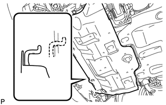
Hook the No. 1 engine under cover sub-assembly to the vehicle body as shown in the illustration.
Install the 4 bolts.
29 N*m
296 kgf*cm
21 ft.*lbf
-
INSTALL LOWER FRONT BUMPER COVER
Install the lower front bumper cover with the 5 bolts and clip.
8.0 N*m
82 kgf*cm
71 in.*lbf