MONITOR SYSTEM
-
FUNCTION OF MAIN COMPONENTS
Component Function Rear Television Camera Assembly Transmits a video signal representing the area behind the vehicle to the radio and display receiver assembly. Radio and Display Receiver Assembly
-
Receives signals from the park/neutral position switch assembly and turns the rear television camera assembly on and off.*1
-
Receives signals from the back-up light switch assembly and turns the rear television camera assembly on and off.*2
-
Displays the image transmitted by the rear television camera assembly on the screen.
Park/Neutral Position Switch Assembly*1 Sends a shift R position signal to the radio and display receiver assembly. Back-up Light Switch Assembly*2 Transmits the on/off signal of the back-up light switch assembly to the radio and display receive assembly.
-
*1: Models with automatic transaxle or CVT
-
*2: Models with manual transaxle
-
-
OPERATING CONDITION
-
Operating Condition
-
The ignition switch is ON.
-
The shift lever is moved to R.
-
The back door is closed.
-
-
-
FUNCTION
-
Area Displayed on Screen
-
On the display, objects on the right of the vehicle appear on the right side of the display panel, and objects on the left of the vehicle appear on the left side of the display panel.
-
The rear television camera assembly uses a wide-angle lens. The perceived distance from images that appear on the screen differs from the actual distance.
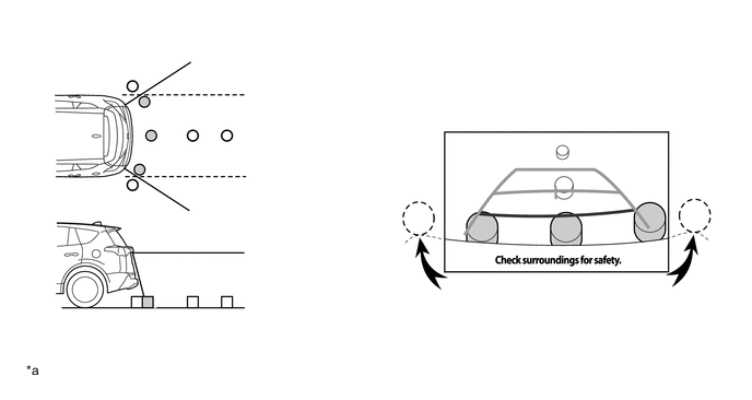
*a The illustrations shown are examples only. The illustrations may differ from the actual vehicle screens. - - Tech Tips
-
The area displayed on the screen may vary in accordance with vehicle status or road conditions.
-
The area covered by the rear television camera assembly is limited. The rear television camera assembly does not show objects close to either corner of the bumper or show the area under the bumper.
-
-
-
-
DIAGNOSIS
-
The rear view monitor system is equipped with a diagnosis function which can display the diagnosis menus. For details, refer to the Repair Manual.
-