HYBRID CONTROL SYSTEM, Diagnostic DTC:P0C76-523
| DTC Code | DTC Name |
|---|---|
| P0C76-523 | Hybrid Battery System Discharge Time Too Long |
DESCRIPTION
Refer to the description for DTC P0D2F-266 Click here.
| DTC No. | INF Code | DTC Detection Condition | Trouble Area |
|---|---|---|---|
| P0C76 | 523 | Inverter voltage (VH) sensor offset malfunction | Inverter with converter assembly |
Tech Tips
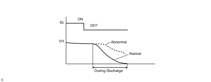
When the power switch is turned off, the MG ECU applies current to MG2 in a way that does not generate torque, in order to discharge the residual voltage in the inverter. When the hybrid system is normal, the VH value is almost 0 V after discharge. This DTC will be stored if the VH value is more than the specified value after discharge.
CAUTION / NOTICE / HINT
Tech Tips
After the repair, clear the DTCs and perform the following procedure to check that DTCs are not output.
-
Turn the power switch off and wait for 30 seconds or more.
-
Turn the power switch on (READY) and wait for 30 seconds or more.
-
Turn the power switch off and wait for 30 seconds or more.
PROCEDURE
-
CHECK DTC OUTPUT (HYBRID CONTROL)
-
Connect the GTS to the DLC3.
-
Turn the power switch on (IG).
-
Enter the following menus: Powertrain / Hybrid Control / Trouble Codes.
-
Check if DTCs are output.
Result Result Proceed to DTC P0C76-523 only is output, or DTCs other than the ones in the table below are also output. A Any of the following DTCs are also output. B DTC No. Relevant Diagnosis P06B0-163 Sensor Power Supply "A" Circuit/Open P06D6-511 Sensor Reference Voltage "F" Circuit/Open P06E6-164 Sensor Power Supply "C" Circuit/Open P0A1A-151, 658, 791 Generator Control Module P0A1B-786, 794 Drive Motor "A" Control Module P0A1D-148 Hybrid Powertrain Control Module P0A3F-243 Drive Motor "A" Position Sensor Circuit P0A40-500 Drive Motor "A" Position Sensor Circuit Range/Performance P0A41-245 Drive Motor "A" Position Sensor Circuit Low P0A4B-253 Generator Position Sensor Circuit P0A4C-513 Generator Position Sensor Circuit Range/Performance P0A4D-255 Generator Position Sensor Circuit Low P0ADC-226 Hybrid Battery Positive Contactor Control Circuit High P0AE0-228 Hybrid Battery Negative Contactor Control Circuit High P0AE7-224 Hybrid Battery Precharge Contactor Control Circuit High P0D2F-266 Drive Motor "A" Inverter Voltage Sensor Circuit Low P0D30-267 Drive Motor "A" Inverter Performance P1C2A-155 Generator A/D Converter Circuit P1CA6-156 Generator Control Module Malfunction P1CA7-193 Drive Motor Control Module Malfunction P1CAC-200 Generator Position Sensor Angle Malfunction P1CAD-168 Drive Motor "A" Position Sensor Angle Malfunction P1CAF-792 Generator Position Sensor REF Signal Cycle Malfunction P1CB0-795 Drive Motor "A" Position Sensor REF Signal Cycle Malfunction P1CB2-793 Generator Position Sensor REF Signal Stop Malfunction P1CB3-796 Drive Motor "A" Position Sensor REF Signal Stop Malfunction P2511-149 HV CPU Power Relay Sense Circuit Intermittent No Continuity P3133-659 Communication Error from Generator to Drive Motor "A" P3134-661 Communication Error from Drive Motor "A" to Generator P324E-788 MG-ECU Power Relay Intermittent Circuit U0110 (all INF codes)*1 Lost Communication with Drive Motor Control Module "A" Tech Tips
-
*1: If any INF codes are output for this DTC, refer to the corresponding diagnostic procedure.
-
P0C76-523 may be output due to a malfunction which causes the DTCs in the table above to be output. In this case, first troubleshoot the output DTCs in the table above. Then, perform a reproduction test to check that no DTCs are output.
-
-
Turn the power switch off.
A 
REFER TO REPLACE INVERTER WITH CONVERTER ASSEMBLY PARTS Click here
B
GO TO DTC CHART (HYBRID CONTROL SYSTEM) Click here
-