METER / GAUGE SYSTEM TERMINALS OF ECU
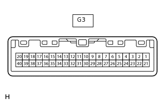
COMBINATION METER ASSEMBLY
Measure the voltage and resistance according to the value(s) in the table below.
Terminal No. (Symbol)
Wiring Color
Terminal Description
Condition
Specified Condition
G3-1 (EP) - Body ground
W-B - Body ground
Ground
Always
Below 1 V
G3-3 (ILL-) - Body ground
GR - Body ground
Illumination signal
Engine switch on (IG), light control switch off
11 to 14 V
Engine switch on (IG), light control switch in tail or head position
Below 1 V
G3-6 (RHUP) - Body ground
B - Body ground
Light control rheostat signal (Light control rheostat up switch)
Engine switch on (IG), up switch pressed
Below 1 V
Engine switch on (IG), up switch not pressed
11 to 14 V
G3-7 (RHDW) - Body ground
P - Body ground
Light control rheostat signal (Light control rheostat down switch)
Engine switch on (IG), down switch pressed
Below 1 V
Engine switch on (IG), down switch not pressed
11 to 14 V
G3-8 (TIRE) - Body ground
Y - Body ground
Tire pressure warning light signal
Engine switch on (IG), tire pressure warning light off
3.2 V or higher
Engine switch on (IG), tire pressure warning light blinks
Below 3.2 V
G3-9 (L) - Body ground
B - Body ground
Fuel sender gauge signal
Fuel F (full tank) → E (empty)
Below 1 V → 4.5 to 9 V
G3-11 (RSET) - Body ground
P - Body ground
ODO/TRIP switch signal
Engine switch on (IG), ODO/TRIP switch on (Pushed)
Below 1 Ω
Engine switch on (IG), ODO/TRIP switch off (Not pushed)
1 MΩ or higher
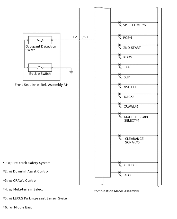
G3-12 (P/SB) - Body ground
L - Body ground
Front passenger seat belt signal
Engine switch on (IG), passenger seat occupied, Seat belt fastened
11 to 14 V
Engine switch on (IG), passenger seat occupied, seat belt unfastened
Below 1 V ←→ 11 to 14 V
G3-15 (OIL) - Body ground
G - Body ground
Engine oil level sensor signal
Engine switch on (IG), engine oil level warning display off
11 to 14 V
Engine switch on (IG), engine oil level warning display on
Below 1 V
G3-19 (B) - Body ground
Y - Body ground
Turn signal LH
Engine switch on (IG), turn signal switch neutral position
Below 1 V
Engine switch on (IG), turn LH indicator light blinks
Below 1 V ←→ 11 to 14 V
G3-20 (B) - Body ground
G - Body ground
Turn signal RH
Engine switch on (IG), turn signal switch neutral position
Below 1 V
Engine switch on (IG), turn RH indicator light blinks
Below 1 V ←→ 11 to 14 V
G3-21 (E2) - Body ground
BR - Body ground
Signal ground
Always
Below 1 V
G3-23 (E) - Body ground
W - Body ground
Fuel sender gauge ground
Always
Below 1 Ω
G3-25 (B) - Body ground
L - Body ground
Battery
Always
11 to 14 V
G3-27 (IG+) - Body ground
R - Body ground
Engine switch signal
Engine switch off
Below 1 V
Engine switch on (IG)
11 to 14 V
G3-29 (S) - Body ground
V - Body ground
Oil pressure switch signal
Engine switch on (IG), oil pressure warning display off
11 to 14 V
Engine switch on (IG), oil pressure warning display on
Below 1 V
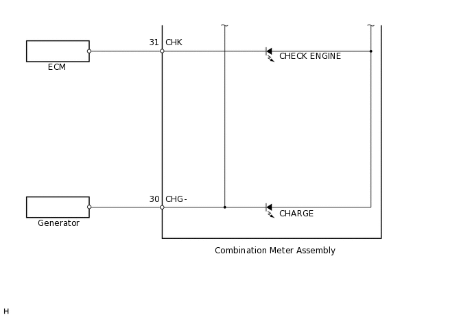
G3-30 (CHG-) - Body ground
P - Body ground
Charge warning light signal
Engine switch on (IG), charge warning light off
11 to 14 V
Engine switch on (IG), charge warning light on
Below 1 V
G3-31 (CHK) - Body ground
V - Body ground
MIL (Malfunction Indicator Lamp) signal
Engine switch on (IG), MIL (Malfunction Indicator Lamp) off
11 to 14 V
Engine switch on (IG), MIL (Malfunction Indicator Lamp) on
Below 1 V
G3-32 (+S) - Body ground
R - Body ground
Speed signal for other systems (Output)
Engine switch on (IG), front wheel turned slowly
Pulse generation
(See waveform 1)
G3-33 (SI) - Body ground
V - Body ground
Speed signal for other systems (Input)
Engine switch on (IG), front wheel turned slowly
Pulse generation
(See waveform 1)
G3-34 (WLVL) - Body ground
W - Body ground
Washer level warning switch signal
Engine switch on (IG), washer level warning display off
11 to 14 V
Engine switch on (IG), washer level warning display comes on
Below 1 V
G3-37 (LIN) - Body ground
GR - Body ground
LIN communication signal
Engine switch on (IG)
Pulse generation
G3-39 (CANL) - Body ground
W - Body ground
CAN communication signal
Engine switch off
200 Ω or higher
G3-40 (CANH) - Body ground
LG - Body ground
CAN communication signal
Engine switch off
200 Ω or higher
-
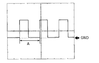
Using an oscilloscope, check waveform 1.
Table 1. Waveform 1 (Reference) Item
Condition
Tool setting
5 V/DIV., 20 ms./DIV.
Vehicle condition
Driving at approximately 20 km/h (12 mph)
Tip:When the system is functioning normally, one wheel revolution generates 4 pulses. As the vehicle speed increases, the width indicated by A in the illustration narrows.
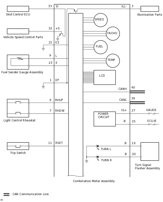
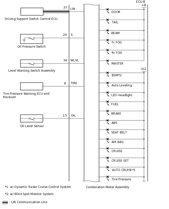
COMBINATION METER ASSEMBLY INNER CIRCUIT
Terminal No. (Symbol) |
Wire Harness Side |
|
|---|---|---|
G3 |
1 (EP) |
Ground |
2 |
- |
|
3 (ILL-) |
Each part that uses illumination signal |
|
4 |
- |
|
5 |
- |
|
6 (RHUP) |
Light control rheostat |
|
7 (RHDW) |
Light control rheostat |
|
8 (TIRE) |
Tire pressure warning ECU and receiver |
|
9 (L) |
Fuel sender gauge assembly |
|
10 |
- |
|
11 (RSET) |
ODO/TRIP switch |
|
12 (P/SB) |
Front seat inner belt assembly |
|
13 |
- |
|
14 |
- |
|
15 (OIL) |
Oil level sensor |
|
16 |
- |
|
17 |
- |
|
18 (WRNP) |
Passenger side seat belt indicator light |
|
19 (B) |
Turn signal flasher assembly |
|
20 (B) |
Turn signal flasher assembly |
|
21 (E2) |
Ground |
|
22 |
- |
|
23 (E) |
Fuel sender gauge assembly |
|
24 |
- |
|
25 (B) |
Battery |
|
26 |
- |
|
27 (IG+) |
GAUGE fuse |
|
28 |
- |
|
29 (S) |
Oil pressure switch |
|
30 (CHG-) |
Generator |
|
31 (CHK) |
ECM |
|
32 (+S) |
Each part that uses vehicle speed signal |
|
33 (SI) |
Skid control ECU |
|
34 (WLVL) |
Level warning switch assembly |
|
36 |
- |
|
37 (LIN) |
Driving support switch control ECU |
|
38 |
- |
|
39 (CANL) |
CAN communication line |
|
40 (CANH) |
CAN communication line |
|