AUTOMATIC HIGH BEAM SYSTEM TERMINALS OF ECU
-
CHECK INSTRUMENT PANEL JUNCTION BLOCK ASSEMBLY AND MAIN BODY ECU (MULTIPLEX NETWORK BODY ECU)
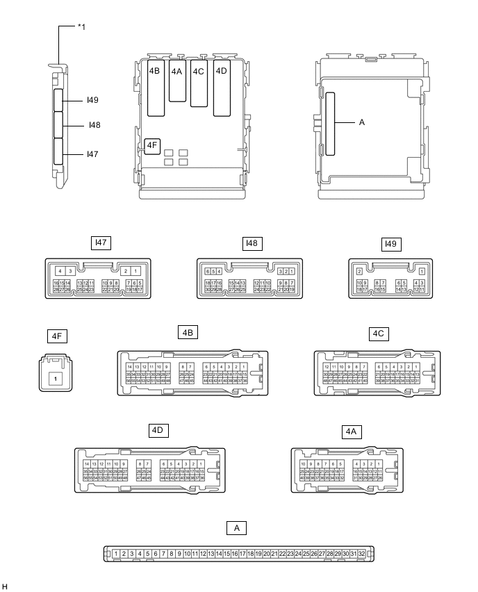
*1 Main Body ECU (Multiplex Network Body ECU) - -
-
Measure the voltage and check for pulses according to the value(s) in the table below.
Terminal No. (Symbol) Wiring Color Terminal Description Condition Specified Condition I48-1 (DIM) - Body ground L - Body ground High beam headlight drive output Engine switch off Below 1 V Engine switch on (IG) 11 to 14 V I48-8 (A) - Body ground G - Body ground Light control switch Auto position signal input Light control switch in Auto position Below 1 V Light control switch not in Auto position 11 to 14 V I47-23 (AHBI) - Body ground P - Body ground Combination switch assembly (automatic high beam main switch) signal input Combination switch assembly (automatic high beam main switch) on Below 1 V Combination switch assembly (automatic high beam main switch) off 11 to 14 V I48-24 (HU) - Body ground Y - Body ground Headlight dimmer switch high position signal input Headlight dimmer switch in high position Below 1 V Headlight dimmer switch not in high position 11 to 14 V I48-19 (CLTB) - I48-21 (CLTE) W - V Automatic light control sensor power supply output Engine switch off Below 1 V Engine switch on (IG) 11 to 14 V I48-20 (CLTS) - Body ground P - Body ground Automatic light control sensor signal input Engine switch off Below 1 V Automatic light control system operating Pulse generation
(See waveform 1)
-
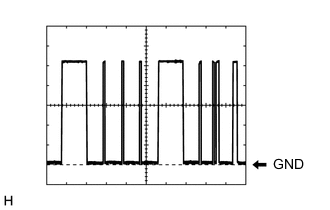
Waveform 1
Item Content Terminal No. (Symbol) I48-20 (CLTS) - Body ground Tool Setting 2 V/DIV., 10 ms./DIV. Condition Automatic light control system operating Tech Tips
The communication waveform changes according to the surrounding brightness.
-
-
CHECK FORWARD RECOGNITION CAMERA