SFI SYSTEM(w/o Canister Pump Module) FREEZE FRAME DATA
DESCRIPTION
The ECM records vehicle and driving condition information as freeze frame data the moment a DTC is stored. When troubleshooting, freeze frame data can be helpful in determining whether the vehicle was moving or stationary, whether the engine was warmed up or not, whether the air fuel ratio was lean or rich, as well as other data recorded at the time of a malfunction.
Tip:If it is impossible to replicate the problem even though a DTC is detected, confirm the freeze frame data.
-
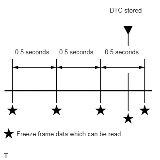
The ECM records engine conditions in the form of freeze frame data every 0.5 seconds. Using the GTS, 5 separate sets of freeze frame data can be checked.
-
3 data sets before the DTC was stored.
1 data set when the DTC was stored.
1 data set after the DTC was stored.
-
These data sets can be used to simulate the condition of the vehicle around the time of the occurrence the malfunction. The data may assist in identifying the cause of the malfunction, and judging whether it was temporary or not.
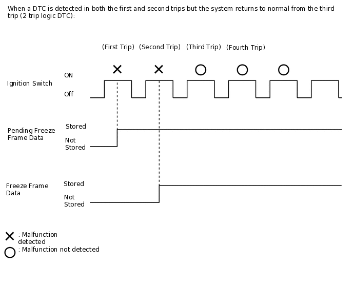
PENDING FREEZE FRAME DATA
Tip:Pending freeze frame data is stored when a 2 trip DTC is first detected during the first trip.
Connect the GTS to the DLC3.
Turn the ignition switch to ON.
Turn the GTS on.
Enter the following menus: Powertrain / Engine and ECT / Trouble Codes.
Select a DTC in order to display its pending freeze frame data.
Powertrain > Engine and ECT > Trouble Codes
Tip:Pending freeze frame data is cleared when any of the following occurs.
-
Using the GTS, the DTCs cleared.
-
The cable is disconnected from the negative (-) battery terminal.
-
40 trips with the engine fully warmed up have been performed after returning to normal. (Pending freeze frame data will not be cleared by only returning the system to normal.)
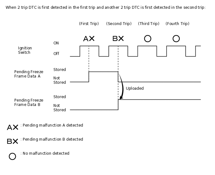
With previous pending freeze frame data stored, if pending freeze frame data is newly stored when a 2 trip DTC is detected in the first trip, the old freeze frame data will be replaced with the new data of the newly detected DTC in the next trip.
LIST OF FREEZE FRAME DATA
Powertrain > Engine and ECT
Tester Display
Measurement Item
Diagnostic Note
Vehicle Speed
Vehicle speed
This is the current vehicle speed.
The vehicle speed is detected using the wheel speed sensors.
-
Vehicle speed data is delayed when it is displayed. Therefore, even if the vehicle speed listed in the freeze frame data is 0 km/h (0 mph), this does not always mean that the malfunction occurred when the vehicle was stopped.
Engine Speed
Engine speed
When the crankshaft position sensor is malfunctioning, "Engine Speed" is approximately 0 rpm or varies greatly from the actual engine speed.
Calculate Load
Load calculated by ECM
This is the engine load calculated based on the estimated intake manifold pressure.
Calculate Load = Estimated intake manifold pressure / maximum intake manifold pressure x 100 (%)
(For example, when the estimated intake pressure is the same as atmospheric pressure, Calculate Load is 100%.)
Vehicle Load
Vehicle load
This is the engine intake air charging efficiency.
Vehicle Load = Current intake airflow (g/rev.) / maximum intake airflow
Maximum intake airflow = Displacement (L) / 2 x 1.2 (g/rev.)
Tip:Due to individual engine differences, intake air temperature, etc., the value may exceed 100%.
Intake airflow (g/rev.) = Intake airflow (gm/sec) x 60 / Engine speed (rpm)
(Intake airflow (gm/sec) is MAF)
MAF
Airflow rate from mass air flow meter sub-assembly
This is the intake air amount from the mass air flow meter sub-assembly.
Atmosphere Pressure
Atmospheric pressure
This value is calculated from the intake air amount.
Standard atmospheric pressure: 101 kPa(abs) [760 mmHg(abs)]
For every 100 m (328 ft) increase in altitude, pressure drops by 1 kPa (7.5 mmHg). This varies by weather.
Coolant Temp
Coolant temperature
This is the engine coolant temperature.
Tip:After warming up the engine, the engine coolant temperature is 75 to 100°C (167 to 212°F).
After a long soak, the engine coolant temperature, intake air temperature and ambient air temperature are approximately equal.
If the value is -40°C (-40°F), or higher than 135°C (275°F), the sensor circuit is open or shorted.
Check if the engine overheats when the value indicates higher than 135°C (275°F).
Intake Air
Intake air temperature
After a long soak, the engine coolant temperature, intake air temperature and ambient air temperature are approximately equal.
If the value is -40°C (-40°F), or higher than 128°C (262°F), the sensor circuit is open or shorted.
Engine Run Time
Engine run time
This is the time elapsed since the engine started.
Tip:The time is counted only while the engine is running.
Initial Engine Coolant Temp
Initial engine coolant temperature
This is the coolant temperature stored when the ignition switch is turned to ON.
Initial Intake Air Temp
Initial intake air temperature
This is the intake air temperature stored when the ignition switch is turned to ON.
Battery Voltage
Battery voltage
If 11 V or less, characteristics of some electrical components may change.
Glow Indicator Supported
Status of the glow indicator supported
-
Glow Indicator
Status of the glow indicator
-
Accel Sens. No.1 Volt %
Absolute accelerator pedal position No. 1
The accelerator pedal position sensor No. 1 output is converted using 5 V = 100%.
Tip:If there are no accelerator pedal position sensor DTCs stored, it is possible to conclude that the accelerator pedal position sensor system is normal.
Accel Sens. No.2 Volt %
Absolute accelerator pedal position No. 2
The accelerator pedal position sensor No. 2 output is converted using 5 V = 100%.
Throttle Sensor Volt %
Absolute throttle position sensor No. 1
The throttle position sensor No. 1 output is converted using 5 V = 100%.
Tip:If there are no throttle position sensor DTCs stored, it is possible to conclude that the throttle position sensor system is normal.
Throttl Sensor #2 Volt %
Throttle sensor position No. 2
The throttle position sensor No. 2 output is converted using 5 V = 100%.
Throttle Sensor Position
Throttle sensor position
This is the throttle valve opening amount used for engine control.
(100% signifies 125° of throttle valve rotation. This does not include the amount the throttle valve is opened to maintain the idle speed during idling.)
This value has no meaning when the ignition switch is ON and the engine is stopped.
The throttle valve opening amount during idling is indicated by 0%. When the throttle valve is fully open, the value is 68%.
Throttle Motor DUTY
Throttle actuator
This is the output duty ratio of the throttle actuator drive circuit.
Throttle Position
Throttle valve opening angle
This value has no meaning when the ignition switch is ON and the engine is stopped.
ISC Flow
Flow rate calculated using information from mass air flow meter sub-assembly
This is the total ISC airflow amount (the amount of intake air necessary to maintain idling).
Tip:ISC Flow (total ISC airflow amount) = ISC Learning Value + ISC Feedback Value + each compensation amount
ISC Position
Requested throttle opening amount calculated using ISC control
This is the throttle valve opening amount while the engine is idling (the throttle valve opening amount necessary to maintain ISC air flow).
ISC Feedback Value
ISC feedback amount
This is the feedback amount necessary to adjust the airflow amount to maintain the target idle speed.
Tip:When the idle speed differs from the target, the feedback amount is adjusted. If the feedback amount becomes more than a certain value, this will be reflected in the ISC learned airflow value.
ISC Learning Value
ISC learned airflow value
This is the learned value of the airflow amount necessary for engine idling.
Tip:If ISC Feedback Value becomes more than a certain value, this will be reflected in ISC Learning Value.
ISC Flow (total ISC airflow amount) = ISC Learning Value + ISC Feedback Value + each compensation amount
Electric Load Feedback Val
Compensation flow rate according to electrical load
This is the ISC compensation amount determined according to the electrical load.
Air Conditioner FB Val
Compensation flow rate according to air conditioner load
This is the ISC compensation amount determined according to the air conditioner load.
Low Revolution Control
Low engine speed control operation state
This parameter indicates whether the engine speed dropped immediately after starting due to poor combustion, etc. This parameter changes to ON when the engine speed drops to below the following speeds 1 to 7 seconds after the engine is started (when the A/C is on, the engine speed thresholds below increase by 100 to 200 rpm).
-
900 rpm (when the engine coolant temperature is 10°C (50°F)).
850 rpm (when the engine coolant temperature is 30°C (86°F)).
750 rpm (when the engine coolant temperature is 60°C (140°F)).
Before 5 seconds elapse after starting the engine, this parameter indicates the status of the previous trip.
After 5 seconds elapse after starting the engine, this parameter indicates the status of the current trip.
Tip:The engine is considered to have started when the engine speed reaches 400 rpm. When the engine speed decreases immediately after starting the engine, this parameter changes to ON and remains ON for the rest of the trip.
ON: The engine speed decreased immediately after starting the engine.
OFF: The engine speed did not decrease immediately after starting the engine.
For use when engine stall, starting problems or rough idle is present.
N Range Status
Shift lever N status
-
Eng Stall Control FB Flow
Intake air compensation flow rate
The intake air amount and ignition timing are adjusted when there is a large decrease in engine speed (for example, a decrease to 550 rpm or less) in order to prevent engine stall.
For use when engine stall, starting problems or rough idle is present.
Deposit Loss Flow
Flow loss due to deposits
This value indicates the amount of compensation for a decrease in flow passage area due to the buildup of deposits on the throttle valve.
Check this value for reference when the engine stalls, is difficult to start, or idles roughly.
When the ISC learned value is initialized, performing the following procedures in order to quickly relearn the Deposit Loss Flow value. After the Deposit Loss Flow has been relearned, gradual fine adjustments will continue automatically.
-
Start the engine cold and allow the engine to idle.
After the engine is warmed up (engine coolant temperature is above 80°C [176°F]), allow the engine to idle for an additional 5 minutes.
Turn the ignition switch off and wait for 30 seconds.
Start the engine again, and allow the engine to idle for 5 minutes.
Injector (Port)
Injection period of the No. 1 cylinder
This is the injection period of the No. 1 cylinder (the command value from the ECM).
Injection Volum (Cylinder1)
Injection volume (cylinder 1)
This is the fuel injection volume for 10 injections.
Fuel Pump/Speed Status
Fuel pump status
-
TCV Status
Intake air control valve actuator for tumble control valve status
This item changes to ON while the tumble control valve is closed.
Current Fuel Type
Current fuel type
-
EVAP (Purge) VSV
Purge VSV control duty
This is the command signal from the ECM.
This is the purge VSV control duty ratio. When EVAP (Purge) VSV is any value except 0%, EVAP purge* is being performed.
EVAP purge*: Gasoline vapor from the fuel tank is being introduced into the intake system via the purge VSV.
When the engine is cold or immediately after the engine is started, EVAP (Purge) VSV is 0%.
Evap Purge Flow
Purge flow
This is the percentage of total engine airflow contributed by EVAP purge operation.
(Evap Purge Flow = Purge flow / Engine airflow x 100 (%))
It is based on MAF and a stored value for airflow and controlled by adjusting the duty cycle for the purge VSV.
Purge Density Learn Value
Purge density learned value
Purge Density Learn Value is the proportion of the decrease in injection volume (based on the change in the air fuel ratio feedback compensation value) related to a 1% purge flow rate.
When Purge Density Learn Value is a large negative value, the purge effect is large.
The purge density is determined from the change in the air fuel ratio feedback compensation value when purge flow is introduced.
Purge density learning is performed so that the feedback compensation value is 0 +/-2%.
Tip:Usually, the value is approximately +/-1%.
1%: The concentration of HC in the purge gas is relatively low.
0%: The concentration of HC in the purge gas is approximately equal to the stoichiometric air fuel ratio.
Large negative values indicate that the concentration of HC in the purge gas is relatively high.
EVAP Purge VSV
VSV status for EVAP control
This parameter displays ON when EVAP (Purge) VSV is 30% or higher, and displays OFF when the VSV duty ratio is less than 30%.
Purge Cut VSV Duty
Purge VSV duty
-
Target Air-Fuel Ratio
Target air fuel ratio
This is the target air fuel ratio used by the ECM.
1.0 is the stoichiometric air fuel ratio. Values that are more than 1 indicate the system attempting to make the air fuel ratio leaner. Values that are less than 1 indicate the system attempting to make the air fuel ratio richer.
Target Air-Fuel Ratio and AF Lambda B1S1 are related.
AF Lambda B1S1
Output air fuel ratio associated with bank 1 sensor 1
This is the actual air fuel ratio calculated based on the air fuel ratio sensor output.
Performing the "Control the Injection Volume" or "Control the Injection Volume for A/F Sensor" function of the Active Test enables the technician to check the voltage output of the sensor.
Results of real-vehicle check when performing the Active Test:
-
Injection Volume: +/-0%
-
AF Lambda B1S1: 0.99
AFS Voltage B1S1: 3.29 V
AFS Current B1S1: 0.00 mA
O2S B1S2: 0.8 V
-
Injection Volume: -12%
-
AF Lambda B1S1: 1.17
AFS Voltage B1S1: 3.91 V
AFS Current B1S1: 0.22 mA
O2S B1S2: 0.015 V
-
Injection Volume: 12%
-
AF Lambda B1S1: 0.93
AFS Voltage B1S1: 2.83 V
AFS Current B1S1: -0.16 mA
O2S B1S2: 0.95 V
AFS Voltage B1S1
Air fuel ratio sensor output voltage for bank 1 sensor 1
This is the voltage output of the air fuel ratio sensor (the voltage cannot be measured at the terminals of the sensor). This value is calculated by the ECM based on the current output of the air fuel ratio sensor (refer to AFS Current below for the actual sensor output).
Performing the Control the Injection Volume or Control the Injection Volume for A/F Sensor function of the Active Test enables the technician to check the voltage output of the sensor.
AFS Current B1S1
Air fuel ratio sensor output current for bank 1 sensor 1
With a stoichiometric air fuel ratio (for example, during idling after the engine is warmed up), the air fuel ratio sensor current output is approximately -0.5 to 0.5 mA.
When the value is outside the range of 0.7 to 2.2 mA when the fuel-cut is being performed, there is a malfunction in the air fuel ratio sensor or sensor circuit.
A/F Heater Duty #1
Air fuel ratio sensor heater duty ratio for bank 1
When the value is any value except 0%, current is being supplied to the heater.
O2S B1S2
Heated oxygen sensor output voltage for bank 1 sensor 2
This is the output voltage of the heated oxygen sensor.
Values close to 0 V indicate an air fuel ratio leaner than the stoichiometric ratio.
Values close to 1 V indicate an air fuel ratio richer than the stoichiometric ratio.
During air fuel ratio feedback control, the value moves back and forth in the range of 0 to 1 V.
Performing the "Control the Injection Volume" or "Control the Injection Volume for A/F Sensor" function of the Active Test enables the technician to check voltage output of the sensor.
Results of real-vehicle check when performing the Active Test:
-
Injection Volume: -12%
-
AF Lambda B1S1: 1.17
AFS Voltage B1S1: 3.91 V
AFS Current B1S1: 0.22 mA
O2S B1S2: 0.015 V
-
Injection Volume: 12%
-
AF Lambda B1S1: 0.93
AFS Voltage B1S1: 2.83 V
AFS Current B1S1: -0.16 mA
O2S B1S2: 0.95 V
O2 Heater B1S2
Heated oxygen sensor heater for bank 1 sensor 2
-
O2 Heater Curr Val B1S2
Heated oxygen sensor current for bank 1 sensor 2
When the value is any value except 0 A, current is being supplied to the heater.
Short FT #1
Short-term fuel trim for bank 1
This item is the "short-term fuel injection volume compensation ratio" used to maintain the air fuel ratio at the stoichiometric ratio using the air fuel ratio sensor for feedback.
Long FT #1
Long-term fuel trim for bank 1
The ECM will learn the Long FT #1 values based on Short FT #1. The goal is to keep Short FT #1 at 0% to keep the air fuel ratio mixture at the stoichiometric ratio.
This value is used to determine whether the system related to air fuel ratio control is malfunctioning.
The condition of the system is determined based on the sum of Short FT #1 and Long FT #1 (excluding times when the system is in transition).
-
15% or higher: There may be a lean air fuel ratio.
-15 to 15%: The air fuel ratio can be determined to be normal.
-15% or less: There may be a rich air fuel ratio.
Air fuel ratio feedback learning is divided up according to the engine operating range (engine speed x load), and a separate value is stored for each operating range. "Long FT #1" indicates the learned value for the current operating range.
[A/F Learn Value Idle #1], [A/F Learn Value Low #1], [A/F Learn Value Mid1 #1], [A/F Learn Value Mid2 #1] and [A/F Learn Value High #1] indicate the learned values for the different operating ranges. The learned value that is the same as "Long FT #1" indicates the current engine operating range.
Total FT #1
Total fuel trim for bank 1
Total FT #1 = Short FT #1 + Long FT #1
Fuel System Status #1
Fuel system status for bank 1
OL (Open Loop): Has not yet satisfied conditions to go to closed loop.
CL (Closed Loop): Uses feedback to perform fuel control.
OLDrive: Open loop due to driving conditions (fuel enrichment).
OLFault: Open loop due to a detected system fault.
CLFault: Closed loop but the air fuel ratio sensor, which is used for fuel control, is malfunctioning.
CL (Closed Loop): During air fuel ratio feedback control, AF Lambda B1S1 is approximately 1.0 and AFS Voltage B1S1 is approximately 3.3 V.
Fuel System Status #2
Fuel system status for bank 2
OL (Open Loop): Has not yet satisfied conditions to go to closed loop.
CL (Closed Loop): Uses feedback to perform for fuel control.
OLDrive: Open loop due to driving conditions (fuel enrichment).
OLFault: Open loop due to a detected system fault.
CLFault: Closed loop but the air fuel ratio sensor, which is used for fuel control, is malfunctioning.
CL (Closed Loop): During air fuel ratio feedback control, AF Lambda B1S1 is approximately 1.0 and AFS Voltage B1S1 is approximately 3.3 V.
IGN Advance
Ignition timing advance for No. 1 cylinder
-
Knock Feedback Value
Knocking feedback value
This is the ignition timing retard compensation amount determined by the presence or absence of knocking.
Ignition timing = Most retarded timing value* + Knock Correct Learn Value* + Knock Feedback Value* + each compensation amount
Example: 21° CA = 10° CA + 14° CA - 3° CA
Most retarded timing value*: The most retarded timing value is a constant determined by the engine speed and engine load.
Knock Correct Learn Value*: The knock correction learned value is calculated as shown below in order to keep Knock Feedback Value as close to -3° CA as possible.
When Knock Feedback Value is less than -4° CA, Knock Correct Learn Value is slowly decreased.
When Knock Feedback Value is more than -2° CA, Knock Correct Learn Value is slowly increased.
Knock Feedback Value*: The base value is -3° CA and is adjusted based on the presence or absence of knocking. When there is no knocking, the value is increased, and when knocking is present, the value is decreased.
-1° CA: There is no knocking and ignition timing is advanced.
-6° CA: Knocking is present and the ignition timing is being retarded.
Tip:If Knock Feedback Value does not change around the time when knocking occurs even though knocking continues (for example, stays at -3° CA), it can be determined that knocking is not being detected.
Possible Causes:
There is a problem with the knock control sensor sensitivity.
The knock control sensor is improperly installed.
There is a problem with a wire harness.
Knock Correct Learn Value
Knocking correction learned value
Refer to "Knock Feedback Value".
When there is knocking or a lack of power, compare the following values to another vehicle of the same model.
-
Engine Speed
Calculate Load
IGN Advance
Knock Feedback Value
Knock Correct Learn Value
Knock Correct Learn Value is large: There is no knocking and the ignition timing is advanced.
Knock Correct Learn Value is small: Knocking is present and the ignition timing is being retarded.
Tip:When knocking continues even though Knock Correct Learn Value is less than that of the vehicle being used for comparison (in other words, the ignition timing is being retarded but the knocking is not stopping), there may be a buildup of deposits or other such problems due to deterioration over time (oil entering the cylinders, poor quality fuel, etc.).
Idle Spark Advn Ctrl #1
Individual cylinder timing advance compensation amount (No. 1)
This is the ignition timing advance compensation amount used to stabilize idling (each cylinder has a separate value). When the speed for a certain cylinder drops, the system advances the timing for that particular cylinder in an attempt to restore the speed and stabilize idling.
It may be possible to use this item to help determine specific cylinders which are not operating normally.
Idle Spark Advn Ctrl #2
Individual cylinder timing advance compensation amount (No. 2)
This is the ignition timing advance compensation amount used to stabilize idling (each cylinder has a separate value). When the speed for a certain cylinder drops, the system advances the timing for that particular cylinder in an attempt to restore the speed and stabilize idling.
It may be possible to use this item to help determine specific cylinders which are not operating normally.
Idle Spark Advn Ctrl #3
Individual cylinder timing advance compensation amount (No. 3)
This is the ignition timing advance compensation amount used to stabilize idling (each cylinder has a separate value). When the speed for a certain cylinder drops, the system advances the timing for that particular cylinder in an attempt to restore the speed and stabilize idling.
It may be possible to use this item to help determine specific cylinders which are not operating normally.
Idle Spark Advn Ctrl #4
Individual cylinder timing advance compensation amount (No. 4)
This is the ignition timing advance compensation amount used to stabilize idling (each cylinder has a separate value). When the speed for a certain cylinder drops, the system advances the timing for that particular cylinder in an attempt to restore the speed and stabilize idling.
It may be possible to use this item to help determine specific cylinders which are not operating normally.
ACIS VSV
VSV status for ACIS (Acoustic Control Induction System) control
This is the ECM control command.
IAC Sensor Voltage
Intake air control valve position sensor output voltage
If the value is 0.2 V or less:
-
The IAC1 circuit is shorted.
The VCIA circuit is open.
If the value is 4.8 V or higher:
-
The VCIA and IAC1 circuits are shorted.
The IAC1 circuit is open.
The EIA1 circuit is open.
Intake Air Control Position
Intake air control valve position
This is the value of the tumble control valve position sensor.
Actual VVT Angle #1
VVT displacement angle for bank 1
This is the VVT displacement angle for the intake camshaft.
This is only available in Freeze Frame Data.
Actual VVT Ex Angle #1
Exhaust VVT displacement angle for bank 1
This is the VVT displacement angle for the exhaust camshaft.
This is only available in Freeze Frame Data.
VVT Control Status #1
Variable Valve Timing (VVT) control status for bank 1
ON: The ECM is sending commands to change the timing (even when the timing is advanced, when the timing is being maintained and not being retarded or advanced any further, the value changes to OFF).
OFF: The system is commanding the timing to change to the most retarded timing.
VVT Advance Fail
VVT control failure status
ON: There is an intake VVT timing advance malfunction.
Catalyst Temp B1S1
Catalyst temperature for bank 1 sensor 1
This is the temperature of the front catalyst estimated by the ECM.
This value is included in the conditions used to detect catalyst deterioration (DTC P0420), etc., and should therefore be used as a reference when recreating malfunction conditions.
Catalyst Temp B1S2
Catalyst temperature for bank 1 sensor 2
This is the temperature of the rear catalyst estimated by the ECM.
Starter Signal
Starter signal
-
Power Steering Signal
Power steering switch signal
-
Neutral Position SW Signal
Park/neutral position switch
-
Clutch Switch
Clutch switch
-
Stop Light Switch
Stop light switch
-
A/C Signal
A/C switch status
-
Idle Up Signal
Idle up signal
-
Closed Throttle Position SW
Closed throttle position switch
-
Fuel Cut Condition
Fuel cut condition
-
Immobiliser Communication
Immobiliser communication
-
TC Terminal
TC terminal status
-
Time after DTC Cleared
Time after DTCs cleared
This is the time elapsed after DTCs were cleared (or after the vehicle left the factory). Time elapsed after the ignition switch is turned off is not counted.
Distance from DTC Cleared
Distance driven after DTCs cleared
This is the distance driven after DTCs were cleared (or after the vehicle left the factory).
Warmup Cycle Cleared DTC
Warmup cycles after DTCs cleared
This is the number of warmup cycles after the DTCs were cleared.
This is the number of times the engine was warmed up* after DTCs were cleared (or after the vehicle left the factory).
Warmed up*: An engine warmup is defined as the engine coolant temperature rising 20°C (36°F) or higher and reaching a temperature of 70°C (158°F) or higher after the engine is started.
Dist Batt Cable Disconnect
Distance driven after battery cable disconnected
-
TC and TE1
TC and CG (TE1) terminals of DLC3
-
Total Distance Traveled
Total distance traveled
-
Ignition Trig. Count
Ignition counter
This is the cumulative number of ignitions.
This counter is incremented by one for each ignition (this stops when misfire monitoring stops). This value is cleared every 200 revolutions.
The misfire rate for each cylinder is calculated by dividing the misfire count for each cylinder by Ignition Trig. Count.
The misfire rate for each cylinder = Cylinder 1 to 4 Misfire Count / Ignition Trig. Count
Tip:For 4-cylinder engines, the values range from 0 to 400.
For 6-cylinder engines, the values range from 0 to 600.
For 8-cylinder engines, the values range from 0 to 800.
Cylinder #1 Misfire Count
Misfire count of cylinder 1
This is the misfire count for each individual cylinder.
This counter is increased by one for each misfire and is cleared every 200 revolutions.
Check this item to help determine the malfunctioning cylinder.
Cylinder #2 Misfire Count
Misfire count of cylinder 2
This is the misfire count for each individual cylinder.
This counter is increased by one for each misfire and is cleared every 200 revolutions.
Check this item to help determine the malfunctioning cylinder.
Cylinder #3 Misfire Count
Misfire count of cylinder 3
This is the misfire count for each individual cylinder.
This counter is increased by one for each misfire and is cleared every 200 revolutions.
Check this item to help determine the malfunctioning cylinder.
Cylinder #4 Misfire Count
Misfire count of cylinder 4
This is the misfire count for each individual cylinder.
This counter is increased by one for each misfire and is cleared every 200 revolutions.
Check this item to help determine the malfunctioning cylinder.
All Cylinders Misfire Count
Misfire count of all cylinders
This is the total misfire count of all cylinders.
This counter is increased by one for each misfire, has a maximum value of 255 and is cleared every 1000 revolutions.
Misfire RPM
Engine speed for first misfire range
This is the average engine speed recorded when misfiring occurs.
This value is closer to the actual conditions of the vehicle at the time misfire occurred than the values of engine speed and engine load stored in the freeze frame data. When reproducing malfunction conditions, use this value as a reference.
Misfire Load
Engine load for first misfire range
This is the average engine load recorded when misfiring occurs.
This value is closer to the actual conditions of the vehicle at the time misfire occurred than the values of engine speed and engine load stored in the freeze frame data. When reproducing malfunction conditions, use this value as a reference.
Tip:To convert g/rev to gm/sec: RPM / 60 x g/rev = gm/sec.
Misfire Margin
Misfire monitoring
This is the misfire detection margin.
Misfire Margin = (Misfire detection threshold - maximum engine speed variation) / misfire detection threshold x 100%
When the variation in the engine speed is large and exceeds the misfire detection threshold, the misfire count starts. Misfire margin is a measure of how much the engine speed variation can increase with respect to the threshold before the engine is determined to be misfiring.
A large value means there is a large margin for the engine speed to vary before the engine is determined to be misfiring.
Example:
When the engine is determined to be misfiring, Misfire Margin = -128 to 0%.
Engine Speed (Starter Off)
Engine speed when starter off
This is the engine speed immediately after starting the engine.
Starter Count
Number of times starter turned on after ignition switch turned ON
This is the number of times the starter turned on during the current trip.
Run Dist of Previous Trip
Distance driven during previous trip
Before 5 seconds elapse after starting the engine, which is DTC P1604 (Startability Malfunction) detection duration, this parameter indicates the distance driven during the previous trip.
After 5 seconds elapse after starting the engine, this parameter indicates the distance driven during the current trip calculated from the vehicle speed signal.
Tip:Run Dist of Previous Trip in freeze frame data which were present when the startability malfunction occurred (DTC P1604 detected) indicates the distance driven during the previous trip, but in all other cases, such as for the snapshot data of Data List (real-time measurements), or for freeze frame data which were present when the DTCs other than P1604 were detected, the value indicates the distance driven during the current trip.
Engine Starting Time
Time elapsed before engine starts (after starter turns on until engine speed reaches 400 rpm)
This is the time elapsed after the starter turns on until the engine speed reaches 400 rpm.
This value is cleared 5 seconds after the engine is started and the value is displayed as 0 ms.
Previous Trip Coolant Temp
Engine coolant temperature during previous trip
Before 120 seconds elapse after starting the engine, this parameter indicates the engine coolant temperature at the end of the previous trip.
After 120 seconds elapse after starting the engine, this parameter indicates the engine coolant temperature during the current trip.
Previous Trip Intake Temp
Intake air temperature during previous trip
Before 120 seconds elapse after starting the engine, this parameter indicates the intake air temperature at the end of the previous trip.
After 120 seconds elapse after starting the engine, this parameter indicates the intake air temperature during the current trip.
Engine Oil Temperature
Engine oil temperature (estimated temperature)
-
Previous Trip Eng Oil Temp
Engine oil temperature during previous trip
-
Ambient Temp for A/C
Ambient temperature for A/C
-
Previous Trip Ambient Temp
Ambient temperature during previous trip
-
Engine Start Hesitation
History of hesitation during engine start
This value changes to ON when the engine speed does not reach 500 rpm during cranking.
Low Rev for Eng Start
History of low engine speed after engine start
This item changes to ON when the engine speed drops to 200 rpm or less within approximately 2 seconds of starting the engine.
Minimum Engine Speed
Minimum engine speed
This is the lowest engine speed detected throughout the trip after the engine is started and ISC learning is completed.
For use when engine stall, starting problems or rough idle is present.
Fuel Cut Elps Time
Time elapsed after engine runs at high speed
The time elapsed after a fuel cut after high engine speed has occurred (more than the engine speed at which fuel cut occurs + 500 rpm).
A/F Learn Value Idle #1
Air fuel ratio learn value of idle area for bank 1
Learning is performed when idling with the engine warmed up (engine coolant temperature is 80°C [176°F] or higher).
A/F Learn Value Low #1
Air fuel ratio learn value of low load area for bank 1
Learning is performed when driving with the engine warmed up (engine coolant temperature is 80°C [176°F] or higher) and operating in the low load range (when the range of engine loads is divided into four parts).
A/F Learn Value Mid1 #1
Air fuel ratio learn value of middle1 load area for bank 1
Learning is performed when driving with the engine warmed up (engine coolant temperature is 80°C [176°F] or higher) and operating in the mid-size load range closer to the low load range (when the range of engine loads is divided into four parts).
A/F Learn Value Mid2 #1
Air fuel ratio learn value of middle2 load area for bank 1
Learning is performed when driving with the engine warmed up (engine coolant temperature is 80°C [176°F] or higher) and operating in the mid-size load range closer to the high load range (when the range of engine loads is divided into four parts).
A/F Learn Value High #1
Air fuel ratio learn value of high load area for bank 1
Learning is performed when driving with the engine warmed up (engine coolant temperature is 80°C [176°F] or higher) and operating in the high load range (when the range of engine loads is divided into four parts).
Tumble C.V Duty Ratio
Intake air control valve actuator for tumble control valve duty ratio
This is the intake air control valve actuator for tumble control valve duty ratio.
Electric Fan Motor
Electric fan motors operation status
-
Brake Override System
Brake override system status
-
Electric Cooling Fan High
Electric fan motors high operation status
-
Electric Cooling Fan Low
Electric fan motors low operation status
-
Idle Fuel Cut
Fuel cut at idle
Idle Fuel Cut = "ON" when the throttle valve is fully closed and the engine speed is high.
FC TAU
Fuel cut TAU (fuel cut during very light load)
This is the fuel cut performed under a very light load to prevent the engine combustion from becoming incomplete.
Immobiliser Fuel Cut
Status of immobiliser fuel cut
-
Immobiliser Fuel Cut History
Status of the immobiliser fuel cut history
When DTCP 1604 is output and Immobiliser Fuel Cut History indicates ON, the engine could not start due to immobiliser operation.
Electrical Load Signal 1
Electrical load signal
-
Electrical Load Signal 3
Electrical load signal
-
SPD (NT)
Input turbine speed (speed sensor NT)
The data is displayed in increments of 50 rpm.
SPD (NC)
Counter gear speed (speed sensor NC)
The data is displayed in increments of 50 rpm.
Overdrive Cut Switch #1
Overdrive cut signal for cruise control
-
Shift SW Status (P Range)
Park/neutral position switchstatus
When the shift lever position displayed on the GTS differs from the actual position, the adjustment of the park/neutral position switch or shift cable may be incorrect.
Pattern Switch (PWR/M)
SPORT mode transition availability
-
Shift SW Status (R Range)
Park/neutral position switchstatus
When the shift lever position displayed on the GTS differs from the actual position, the adjustment of the park/neutral position switch or shift cable may be incorrect.
Shift SW Status (N Range)
Park/neutral position switchstatus
When the shift lever position displayed on the GTS differs from the actual position, the adjustment of the park/neutral position switch or shift cable may be incorrect.
Shift SW Status (N,P Range) Supported
Status of park/neutral position switch (N or P) supported
-
Shift SW Status (N,P Range)
Park/neutral position switch status (N or P)
-
Sports Shift Up SW
Sport shift up switch status
-
Sports Shift Down SW
Sport shift down switch status
-
Sports Mode Selection SW
Sport mode select switch status
-
Shift SW Status (D Range)
Park/neutral position switchstatus
When the shift lever position displayed on the GTS differs from the actual position, the adjustment of the park/neutral position switch or shift cable may be incorrect.
A/T Oil Temperature 1
ATF temperature sensor value
If value is -40°C (-40°F) or 150°C (302°F) or more, ATF temperature sensor circuit is open or short.
NT Sensor Voltage
Speed sensor NT output voltage
-
NC Sensor Voltage
Speed sensor NC output voltage
-
Lock Up
Lock-up
-
Shift Status
ECM gearshift command
-
SLT Solenoid Status
Shift solenoid valve SLT status
-
SLU Solenoid Status
Shift solenoid valve SLU status
-
SL Solenoid Status
Shift solenoid valve SL status
-