POWER WINDOW CONTROL SYSTEM(w/o Jam Protection Function) TERMINALS OF ECU
CHECK POWER WINDOW REGULATOR MASTER SWITCH ASSEMBLY
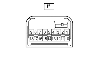
Disconnect the J5 power window regulator master switch assembly connector.
Measure the voltage and resistance according to the value(s) in the table below.
Tip:Measure the values on the wire harness side with the connector disconnected.
Terminal No. (Symbol)
Wiring Color
Terminal Description
Condition
Specified Condition
J5-1 (E) - Body ground
W-B - Body ground
Ground
Always
Below 1 Ω
J5-6 (B) - J5-1 (E)
L - W-B
IG power supply
Ignition switch ON
11 to 14 V
Ignition switch off
Below 1 V
Reconnect the J5 power window regulator master switch assembly connector.
Measure the voltage according to the value(s) in the table below.
Terminal No. (Symbol)
Wiring Color
Terminal Description
Condition
Specified Condition
J5-3 (U) - J5-1 (E)
R - W-B
Driver door power window motor UP output
Ignition switch ON, driver door power window switch off
11 to 14 V
Ignition switch ON, driver door power window switch up (Manual operation)
Below 1 V
J5-4 (D) - J5-1 (E)
GR - W-B
Driver door power window motor DOWN output
Ignition switch ON, driver door power window switch off
11 to 14 V
Ignition switch ON, driver door power window switch down (Manual operation)
Below 1 V
J5-16 (U) - J5-1 (E)
G - W-B
Front passenger power window motor UP output
Ignition switch ON, front passenger door power window switch off
Below 1 V
Ignition switch ON, front passenger door power window switch up (Manual operation)
11 to 14 V
J5-15 (D) - J5-1 (E)
BR - W-B
Front passenger power window motor DOWN output
Ignition switch ON, front passenger door power window switch off
Below 1 V
Ignition switch ON, front passenger door power window switch down (Manual operation)
11 to 14 V
J5-12 (U) - J5-1 (E)
R - W-B
Rear door LH power window motor UP output
Ignition switch ON, rear door LH power window switch off
Below 1 V
Ignition switch ON, rear door LH power window switch up (Manual operation)
11 to 14 V
J5-13 (D) - J5-1 (E)
BE - W-B
Rear door LH power window motor DOWN output
Ignition switch ON, rear door LH power window switch off
Below 1 V
Ignition switch ON, rear door LH power window switch down (Manual operation)
11 to 14 V
J5-10 (U) - J5-1 (E)
G - W-B
Rear door RH power window motor UP output
Ignition switch ON, rear door RH power window switch off
Below 1 V
Ignition switch ON, rear door RH power window switch up (Manual operation)
11 to 14 V
J5-18 (D) - J5-1 (E)
BR - W-B
Rear door RH power window motor DOWN output
Ignition switch ON, rear RH door power window switch off
Below 1 V
Ignition switch ON, rear RH door power window switch down (Manual operation)
11 to 14 V
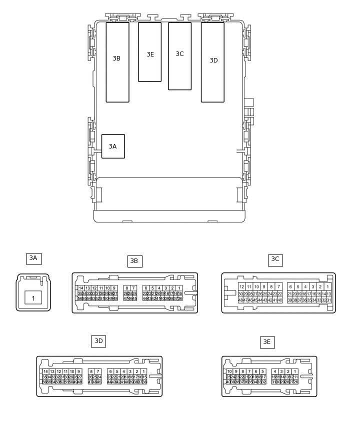
CHECK MAIN BODY ECU (MULTIPLEX NETWORK BODY ECU) AND INSTRUMENT PANEL JUNCTION BLOCK ASSEMBLY
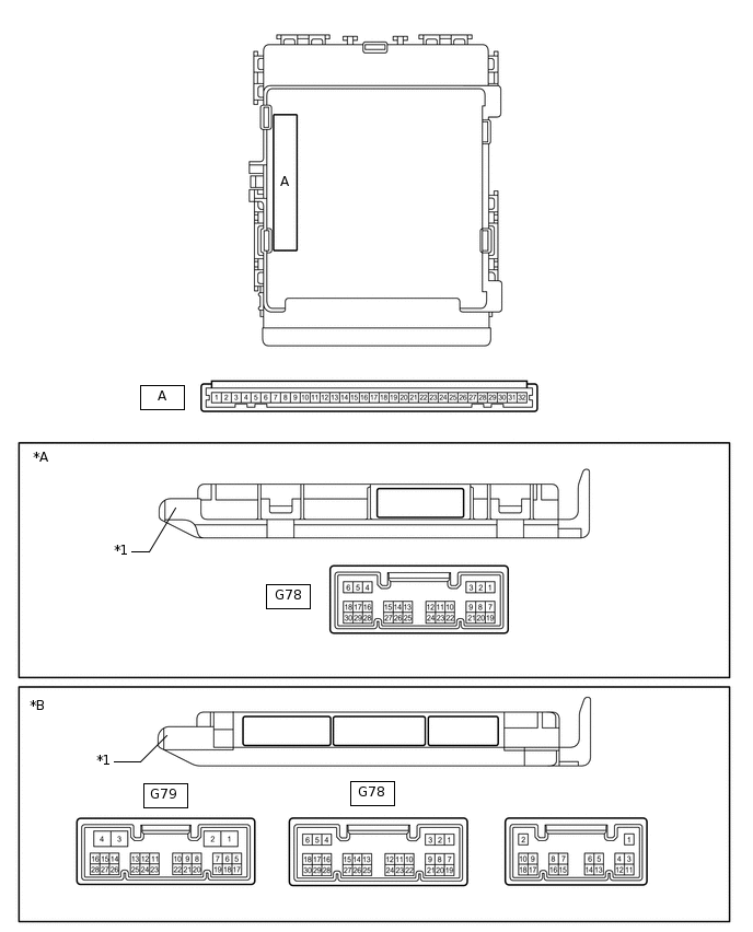
*A
Main Body ECU (Multiplex Network Body ECU) with 1 Connector
*B
Main Body ECU (Multiplex Network Body ECU) with 3 Connectors
*1
Main Body ECU (Multiplex Network Body ECU)
-
-
Remove the main body ECU (multiplex network body ECU).
Connect the instrument panel junction block assembly connectors.
Measure the voltage and resistance according to the value(s) in the table below.
Terminal No. (Symbol)
Wiring Color
Terminal Description
Condition
Specified Condition
A-11 (GND1) - Body ground
None - Body ground
Ground
Always
Below 1 Ω
A-30 (BECU) - Body ground
None - Body ground
Battery power supply
Always
11 to 14 V
A-29 (ACC) - Body ground
None - Body ground
ACC power supply
Ignition switch ACC
11 to 14 V
Ignition switch off
Below 1 V
A-32 (IG) - Body ground
None - Body ground
IG power supply
Ignition switch ON
11 to 14 V
Ignition switch off
Below 1 V
Install the main body ECU (multiplex network body ECU).
Measure the voltage according to the value(s) in the table below.
Terminal No. (Symbol)
Wiring Color
Terminal Description
Condition
Specified Condition
3C-44 - Body ground
R - Body ground
Power window relay operation signal
Ignition switch ON
11 to 14 V
Ignition switch off
Below 1 V