REAR POWER SEAT CONTROL SYSTEM Park / Neutral Position Switch Circuit
| DTC Code | DTC Name |
|---|---|
| Park / Neutral Position Switch Circuit |
DESCRIPTION
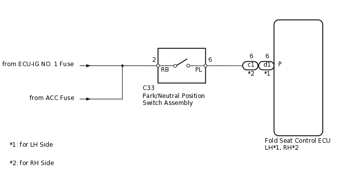
The fold seat control ECU receives signals from the park/neutral position switch and controls the seat folding and return operations. If the shift lever is in any position other than P when the engine switch is on (IG), the seat cannot be operated.
WIRING DIAGRAM
CAUTION / NOTICE / HINT
Inspect the fuses for circuits related to this system before performing the following inspection procedure.
PROCEDURE
CHECK FOLD SEAT CONTROL ECU (PARK/NEUTRAL POSITION SWITCH SIGNAL)
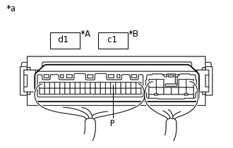
*A
for LH Side
*B
for RH Side
*a
Component with harness connected (Fold Seat Control ECU)
Remove the fold seat control ECU with its connectors still connected.
Measure the voltage according to the value(s) in the table below.
Standard Voltage
Table 1. for LH Side Tester Connection
Condition
Specified Condition
d1-6 (P) - Body ground
Engine switch on (ACC) or on (IG)Shift lever in P
11 to 14 V
Engine switch on (ACC) or on (IG)Shift lever not in P
Below 1 V
Table 2. for RH Side Tester Connection
Condition
Specified Condition
c1-6 (P) - Body ground
Engine switch on (ACC) or on (IG)Shift lever in P
11 to 14 V
Engine switch on (ACC) or on (IG)Shift lever not in P
Below 1 V
Result
Result
OK
NG
CHECK HARNESS AND CONNECTOR (PARK/NEUTRAL POSITION SWITCH - BATTERY)
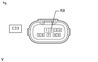
*a
Front view of wire harness connector (to Park/Neutral Position Switch Assembly)
Disconnect the C33 switch connector.
Measure the voltage according to the value(s) in the table below.
Standard Voltage
Tester Connection
Switch Condition
Specified Condition
C33-2 (RB) - Body ground
Engine switch on (ACC) or on (IG)
11 to 14 V
Engine switch off
Below 1 V
Result
Result
OK
NG
NG REPAIR OR REPLACE HARNESS OR CONNECTOR
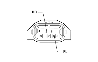
INSPECT PARK/NEUTRAL POSITION SWITCH ASSEMBLY
A750F:
Remove the switch.
A760F:
Remove the switch.
Measure the resistance according to the value(s) in the table below.
Standard Resistance
Tester Connection
Condition
Specified Condition
2 (RB) - 6 (PL)
Shift lever in P
Below 1 Ω
2 (RB) - 6 (PL)
Shift lever not in P
10 kΩ or higher
Result
Result
Proceed to
OK
A
NG (for A750F)
B
NG (for A760F)
C
CHECK HARNESS AND CONNECTOR (FOLD SEAT CONTROL ECU - PARK/NEUTRAL POSITION SWITCH)
Disconnect the d1*1 or c1*2 ECU connector.
*1: for LH Side
*2: for RH Side
Disconnect the C33 switch connector.
Measure the resistance according to the value(s) in the table below.
Standard Resistance
Table 3. for LH Side Tester Connection
Condition
Specified Condition
d1-6 (P) - C33-6 (PL)
Always
Below 1 Ω
d1-6 (P) - Body ground
Always
10 kΩ or higher
Table 4. for RH Side Tester Connection
Condition
Specified Condition
c1-6 (P) - C33-6 (PL)
Always
Below 1 Ω
c1-6 (P) - Body ground
Always
10 kΩ or higher
Result
Result
OK
NG
NG REPAIR OR REPLACE HARNESS OR CONNECTOR