LIN COMMUNICATION SYSTEM TERMINALS OF ECU
-
CHECK INSTRUMENT PANEL JUNCTION BLOCK ASSEMBLY AND MAIN BODY ECU (MULTIPLEX NETWORK BODY ECU)
-
Remove the main body ECU (multiplex network body ECU) from the instrument panel junction block assembly.
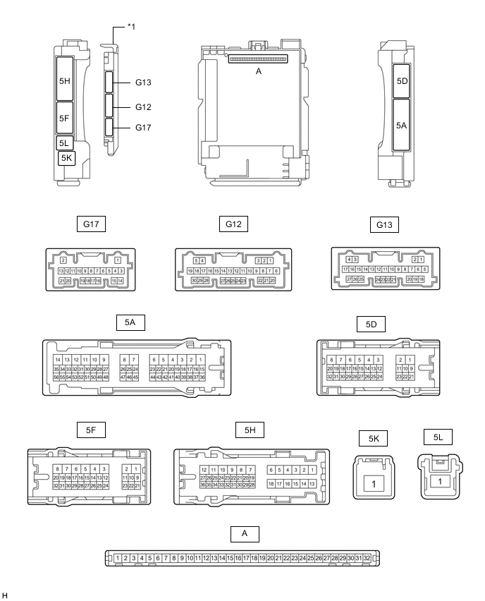
*1 Main Body ECU (Multiplex Network Body ECU) - - -
Reconnect the instrument panel junction block assembly connectors.
-
Measure the voltage and resistance according to the value(s) in the table below.
Tester Connection Wiring Color Terminal Description Condition Specified Condition A-11 (GND1) - Body ground - Ground Always Below 1 Ω A-31 (BECU) - Body ground - Battery power supply Always 11 to 14 V A-30 (ACC) - Body ground - ACC power supply Engine switch on (ACC) 11 to 14 V Engine switch off Below 1 V A-32 (IG) - Body ground - IG power supply Engine switch on (IG) 11 to 14 V Engine switch off Below 1 V -
Install the main body ECU (multiplex network body ECU) to the instrument panel junction block assembly.
-
Measure the pulse according to the value(s) in the table below.
for LHD Tester Connection Wiring Color Terminal Description Condition Specified Condition 5A-19 - Body ground L - Body ground LIN communication line Engine switch on (IG) Pulse generation 5A-20 - Body ground V - Body ground LIN communication line Engine switch on (IG) Pulse generation 5H-34 - Body ground BE - Body ground LIN communication line Engine switch on (IG) Pulse generation 5H-35 - Body ground B - Body ground LIN communication line Engine switch on (IG) Pulse generation for RHD Tester Connection Wiring Color Terminal Description Condition Specified Condition 5A-40 - Body ground L - Body ground LIN communication line Engine switch on (IG) Pulse generation 5H-34 - Body ground B - Body ground LIN communication line Engine switch on (IG) Pulse generation 5H-33 - Body ground LG - Body ground LIN communication line Engine switch on (IG) Pulse generation
-
-
CHECK FRONT MULTIPLEX NETWORK DOOR ECU LH

-
Disconnect the H31 front multiplex network door ECU LH connector.
-
Measure the resistance and voltage according to the value(s) in the table below.
Terminal No. (Symbol) Wiring Color Terminal Description Condition Specified Condition H31-3 (SIG) - Body ground B - Body ground IG power supply Engine switch off Below 1 V Engine switch on (IG) 11 to 14 V H31-4 (CPUB) - Body ground L - Body ground Battery power supply Always 11 to 14 V H31-6 (BDR) - Body ground R - Body ground Battery power supply Always 11 to 14 V H31-1 (GND) - Body ground W-B - Body ground Ground Always Below 1 Ω -
Reconnect the H31 front multiplex network door ECU LH connector.
-
Measure the pulse according to the value(s) in the table below.
Terminal No. (Symbol) Wiring Color Terminal Description Condition Specified Condition H31-11 (LIN1) - Body ground SB - Body ground*1
B - Body ground*2
LIN communication line Engine switch on (IG) Pulse generation H31-13 (LIN3) - Body ground W - Body ground LIN communication line Engine switch on (IG) Pulse generation *1: for LHD
*2: for RHD
-
-
CHECK FRONT MULTIPLEX NETWORK DOOR ECU RH

-
Disconnect the H12 front multiplex network door ECU RH connector.
-
Measure the resistance and voltage according to the value(s) in the table below.
Terminal No. (Symbol) Wiring Color Terminal Description Condition Specified Condition H12-3 (SIG) - Body ground B - Body ground IG power supply Engine switch off Below 1 V Engine switch on (IG) 11 to 14 V H12-4 (CPUB) - Body ground L - Body ground Battery power supply Always 11 to 14 V H12-6 (BDR) - Body ground R - Body ground Battery power supply Always 11 to 14 V H12-1 (GND) - Body ground W-B - Body ground Ground Always Below 1 Ω -
Reconnect the H12 front multiplex network door ECU RH connector.
-
Measure the pulse according to the value(s) in the table below.
Terminal No. (Symbol) Wiring Color Terminal Description Condition Specified Condition H12-11 (LIN1) - Body ground B - Body ground*1
SB - Body ground*2
LIN communication line Engine switch on (IG) Pulse generation H12-13 (LIN3) - Body ground W - Body ground LIN communication line Engine switch on (IG) Pulse generation *1: for LHD
*2: for RHD
-
-
CHECK REAR MULTIPLEX NETWORK DOOR ECU LH

-
Disconnect the K21 rear multiplex network door ECU LH connector.
-
Measure the resistance and voltage according to the value(s) in the table below.
Terminal No. (Symbol) Wiring Color Terminal Description Condition Specified Condition K21-12 (SIG) - Body ground B - Body ground IG power supply Engine switch off Below 1 V Engine switch on (IG) 11 to 14 V K21-11 (CPUB) - Body ground L - Body ground Battery power supply Always 11 to 14 V K21-4 (BDR) - Body ground L - Body ground Battery power supply Always 11 to 14 V K21-1 (GND) - Body ground LA - Body ground Ground Always Below 1 Ω -
Reconnect the K21 rear multiplex network door ECU LH connector.
-
Measure the pulse according to the value(s) in the table below.
Terminal No. (Symbol) Wiring Color Terminal Description Condition Specified Condition K21-22 (LIN1) - Body ground B - Body ground LIN communication line Engine switch on (IG) Pulse generation K21-23 (LIN3) - Body ground L - Body ground LIN communication line Engine switch on (IG) Pulse generation
-
-
CHECK REAR MULTIPLEX NETWORK DOOR ECU RH

-
Disconnect the K7 rear multiplex network door ECU RH connector.
-
Measure the resistance and voltage according to the value(s) in the table below.
Terminal No. (Symbol) Wiring Color Terminal Description Condition Specified Condition K7-12 (SIG) - Body ground L - Body ground IG power supply Engine switch off Below 1 V Engine switch on (IG) 11 to 14 V K7-11 (CPUB) - Body ground L - Body ground Battery power supply Always 11 to 14 V K7-4 (BDR) - Body ground B - Body ground Battery power supply Always 11 to 14 V K7-1 (GND) - Body ground LA - Body ground Ground Always Below 1 Ω -
Reconnect the K7 rear multiplex network door ECU RH connector.
-
Measure the pulse according to the value(s) in the table below.
Terminal No. (Symbol) Wiring Color Terminal Description Condition Specified Condition K7-22 (LIN1) - Body ground B - Body ground LIN communication line Engine switch on (IG) Pulse generation K7-23 (LIN3) - Body ground L - Body ground LIN communication line Engine switch on (IG) Pulse generation
-
-
CHECK MULTIPLEX NETWORK MASTER SWITCH ASSEMBLY
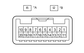
*A for LHD *B for RHD
-
Disconnect the I5*1 or I2*2 multiplex network master switch assembly connector.
-
*1: for LHD
-
*2: for RHD
-
-
Measure the resistance and voltage according to the value(s) in the table below.
for LHD Terminal No. (Symbol) Wiring Color Terminal Description Condition Specified Condition I5-11 (B) - Body ground LA-GR - Body ground Battery power supply Always 11 to 14 V I5-12 (GND) - Body ground LA-R - Body ground Ground Always Below 1 Ω for RHD Terminal No. (Symbol) Wiring Color Terminal Description Condition Specified Condition I2-11 (B) - I2-12 (GND) LA-GR - LA-R Power supply Always 11 to 14 V I2-12 (GND) - Body ground LA-R - Body ground Ground Always Below 1 Ω -
Reconnect the I5*1 or I2*2 multiplex network master switch assembly connector.
-
*1: for LHD
-
*2: for RHD
-
-
Measure the pulse according to the value(s) in the table below.
for LHD Terminal No. (Symbol) Wiring Color Terminal Description Condition Specified Condition I5-17 (LIN1) - Body ground SB - Body ground LIN communication line Engine switch on (IG) Pulse generation for RHD Terminal No. (Symbol) Wiring Color Terminal Description Condition Specified Condition I2-17 (LIN1) - Body ground SB - Body ground LIN communication line Engine switch on (IG) Pulse generation
-
-
CHECK FRONT POWER WINDOW REGULATOR MOTOR ASSEMBLY LH

-
Disconnect the H21 front power window regulator motor assembly LH connector.
-
Measure the resistance and voltage according to the value(s) in the table below.
Terminal No. (Symbol) Wiring Color Terminal Description Condition Specified Condition H21-1 (GND) - Body ground LA-B - Body ground Ground Always Below 1 Ω H21-2 (B) - Body ground LA-L - Body ground*1
LA-R - Body ground*2
Battery power supply Always 11 to 14 V *1: for LHD
*2: for RHD
-
Reconnect the H21 front power window regulator motor assembly LH connector.
-
Measure the pulse according to the value(s) in the table below.
Terminal No. (Symbol) Wiring Color Terminal Description Condition Specified Condition H21-9 (LIN) - Body ground W - Body ground LIN communication line Engine switch on (IG) Pulse generation
-
-
CHECK FRONT POWER WINDOW REGULATOR MOTOR ASSEMBLY RH

-
Disconnect the H2 front power window regulator motor assembly RH connector.
-
Measure the resistance and voltage according to the value(s) in the table below.
Terminal No. (Symbol) Wiring Color Terminal Description Condition Specified Condition H2-1 (GND) - Body ground LA-B - Body ground Ground Always Below 1 Ω H2-2 (B) - Body ground LA-R - Body ground*1
LA-L - Body ground*2
Battery power supply Always 11 to 14 V *1: for LHD
*2: for RHD
-
Reconnect the H2 front power window regulator motor assembly RH connector.
-
Measure the pulse according to the value(s) in the table below.
Terminal No. (Symbol) Wiring Color Terminal Description Condition Specified Condition H2-9 (LIN) - Body ground W - Body ground LIN communication line Engine switch on (IG) Pulse generation
-
-
CHECK REAR POWER WINDOW REGULATOR MOTOR ASSEMBLY LH

-
Disconnect the K15 rear power window regulator motor assembly LH connector.
-
Measure the resistance and voltage according to the value(s) in the table below.
Terminal No. (Symbol) Wiring Color Terminal Description Condition Specified Condition K15-1 (GND) - Body ground LA-B - Body ground Ground Always Below 1 Ω K15-2 (B) - Body ground LA-B - Body ground Battery power supply Always 11 to 14 V -
Reconnect the K15 rear power window regulator motor assembly LH connector.
-
Measure the pulse according to the value(s) in the table below.
Terminal No. (Symbol) Wiring Color Terminal Description Condition Specified Condition K15-9 (LIN) - Body ground L - Body ground LIN communication line Engine switch on (IG) Pulse generation
-
-
CHECK REAR POWER WINDOW REGULATOR MOTOR ASSEMBLY RH
-
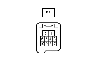
Disconnect the K1 rear power window regulator motor assembly RH connector.
-
Measure the resistance and voltage according to the value(s) in the table below.
Terminal No. (Symbol) Wiring Color Terminal Description Condition Specified Condition K1-1 (GND) - Body ground LA-B - Body ground Ground Always Below 1 Ω K1-2 (B) - Body ground LA-BE - Body ground Battery power supply Always 11 to 14 V -
Reconnect the K1 rear power window regulator motor assembly RH connector.
-
Measure the pulse according to the value(s) in the table below.
Terminal No. (Symbol) Wiring Color Terminal Description Condition Specified Condition K1-9 (LIN) - Body ground L - Body ground LIN communication line Engine switch on (IG) Pulse generation
-
-
CHECK CERTIFICATION ECU (SMART KEY ECU ASSEMBLY)
-
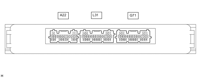
Disconnect the G71 certification ECU (smart key ECU assembly) connector.
-
Measure the resistance and voltage according to the value(s) in the table below.
Terminal No. (Symbol) Wiring Color Terminal Description Condition Specified Condition G71-4 (+B) - Body ground W - Body ground Battery power supply Always 11 to 14 V G71-18 (E) - Body ground W-B - Body ground Ground Always Below 1 Ω -
Reconnect the G71 certification ECU (smart key ECU assembly) connector.
-
Measure the pulse according to the value(s) in the table below.
Terminal No. (Symbol) Wiring Color Terminal Description Condition Specified Condition G71-13 (LIN) - Body ground G - Body ground LIN communication line Engine switch on (IG) Pulse generation
-
-
CHECK STEERING LOCK ACTUATOR OR UPPER BRACKET ASSEMBLY
-
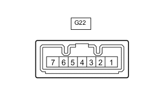
Disconnect the G22 steering lock actuator or upper bracket assembly connector.
-
Measure the resistance and voltage according to the value(s) in the table below.
Terminal No. (Symbol) Wiring Color Terminal Description Condition Specified Condition G22-1 (GND) - Body ground W-B - Body ground Ground Always Below 1 Ω G22-6 (IG2) - Body ground R - Body ground IG power supply Engine switch off Below 1 V Engine switch on (IG) 11 to 14 V G22-7 (B) - Body ground B - Body ground Battery power supply Always 11 to 14 V -
Reconnect the G22 steering lock actuator or upper bracket assembly connector.
-
Measure the pulse according to the value(s) in the table below.
Terminal No. (Symbol) Wiring Color Terminal Description Condition Specified Condition G22-5 (LIN) - Body ground V - Body ground LIN communication line Engine switch on (IG) Pulse generation
-
-
CHECK ID CODE BOX (IMMOBILISER CODE ECU)
-
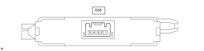
Disconnect the G58 ID code box (immobiliser code ECU) connector.
-
Measure the resistance and voltage according to the value(s) in the table below.
Terminal No. (Symbol) Wiring Color Terminal Description Condition Specified Condition G58-1 (+B) - Body ground LA-GR - Body ground Battery power supply Always 11 to 14 V G58-5 (GND) - Body ground LA - Body ground Ground Always Below 1 Ω -
Reconnect the G58 ID code box (immobiliser code ECU) connector.
-
Measure the pulse according to the value(s) in the table below.
Terminal No. (Symbol) Wiring Color Terminal Description Condition Specified Condition G58-2 (LIN1) - Body ground L - Body ground LIN communication line Engine switch on (IG) Pulse generation
-
-
CHECK SLIDING ROOF DRIVE GEAR SUB-ASSEMBLY (w/ Sliding Roof System)
-
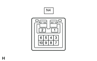
Disconnect the N4 sliding roof drive gear sub-assembly connector.
-
Measure the resistance and voltage according to the value(s) in the table below.
Terminal No. (Symbol) Wiring Color Terminal Description Condition Specified Condition N4-1 (B) - Body ground LA-G - Body ground Battery power supply Always 11 to 14 V N4-2 (E) - Body ground LA-G - Body ground Ground Always Below 1 Ω -
Reconnect the N4 sliding roof drive gear sub-assembly connector.
-
Measure the pulse according to the value(s) in the table below.
Terminal No. (Symbol) Wiring Color Terminal Description Condition Specified Condition N4-7 (MPX1) - Body ground V - Body ground LIN communication line Engine switch on (IG) Pulse generation
-
-
CHECK KICK DOOR CONTROL SENSOR (w/ Hands Free Power Trunk Lid)
-
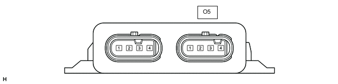
Disconnect the O5 kick door control sensor connector.
-
Measure the resistance and voltage according to the value(s) in the table below.
Terminal No. (Symbol) Wiring Color Terminal Description Condition Specified Condition O5-1 (B) - Body ground L - Body ground Battery power supply Always 11 to 14 V O5-4 (GND) - Body ground W-B - Body ground Ground Always Below 1 Ω -
Reconnect the O5 kick door control sensor connector.
-
Measure the pulse according to the value(s) in the table below.
Terminal No. (Symbol) Wiring Color Terminal Description Condition Specified Condition O5-2 (LIN) - Body ground SB - Body ground LIN communication line Engine switch on (IG) Pulse generation
-
-
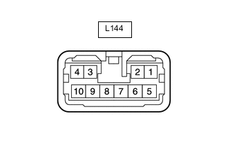
CHECK REAR SIDE WINDOW CURTAIN ASSEMBLY LH (w/ Side Window Curtain)
-
Disconnect the L144 rear side window curtain assembly LH connector.
-
Measure the resistance and voltage according to the value(s) in the table below.
Terminal No. (Symbol) Wiring Color Terminal Description Condition Specified Condition L144-3 (B) - Body ground LA-B - Body ground Battery power supply Always 11 to 14 V L144-10 (E) - Body ground LA - Body ground Ground Always Below 1 Ω -
Reconnect the L144 rear side window curtain assembly LH connector.
-
Measure the pulse according to the value(s) in the table below.
Terminal No. (Symbol) Wiring Color Terminal Description Condition Specified Condition L144-6 (LIN) - Body ground LA-SB - Body ground LIN communication line Engine switch on (IG) Pulse generation
-
-
CHECK REAR SIDE WINDOW CURTAIN ASSEMBLY RH (w/ Side Window Curtain)

-
Disconnect the L143 rear side window curtain assembly RH connector.
-
Measure the resistance and voltage according to the value(s) in the table below.
Terminal No. (Symbol) Wiring Color Terminal Description Condition Specified Condition L143-3 (B) - Body ground LA-B - Body ground Battery power supply Always 11 to 14 V L143-10 (E) - Body ground LA - Body ground Ground Always Below 1 Ω -
Reconnect the L143 rear side window curtain assembly RH connector.
-
Measure the pulse according to the value(s) in the table below.
Terminal No. (Symbol) Wiring Color Terminal Description Condition Specified Condition L143-6 (LIN) - Body ground LA-SB - Body ground LIN communication line Engine switch on (IG) Pulse generation
-