AUTOMATIC TRANSMISSION SYSTEM(for 8GR-FKS), Diagnostic DTC:P271312
| DTC Code | DTC Name |
|---|---|
| P271312 | Pressure Control Solenoid "D" Circuit Short to Battery |
DESCRIPTION
Refer to DTC P27137F.
| DTC No. | Detection Item | DTC Detection Condition | Trouble Area | MIL | Memory | Note |
|---|---|---|---|---|---|---|
| P271312 | Pressure Control Solenoid "D" Circuit Short to Battery | Either condition is met (1-trip detection logic):
|
|
Comes on | DTC stored | SAE: P2721 |
| Vehicle Condition | |||
|---|---|---|---|
| Pattern 1 | Pattern 2 | ||
| Diagnostic Condition | Engine is running. | ○ | ○ |
| Malfunction Condition | Solenoid (SLT) valve circuit current is higher than specified value for the target current. | ○ | - |
| SLT negative (-) terminal monitor is abnormal. | - | ○ | |
| Duration | 1 second or more | 1.3 seconds or more | |
| Detection Logic | 1-trip detection logic | 1-trip detection logic | |
Tech Tips
This DTC is stored when either of the above detection patterns is met.
MONITOR DESCRIPTION
When a short in the solenoid (SLT) valve circuit is detected, the ECM will determine that there is a malfunction, illuminate the MIL and store this DTC.
CONFIRMATION DRIVING PATTERN
Tech Tips
After repair has been completed, clear the DTC and then check that the vehicle has returned to normal by performing the following All Readiness check procedure.
-
Connect the GTS to the DLC3.
-
Turn the engine switch on (IG) and turn the GTS on.
-
Clear the DTCs (even if no DTCs are stored, perform the clear DTC procedure).
-
Turn the engine switch off and wait for at least 30 seconds.
-
Turn the engine switch on (IG) and turn the GTS on.
-
Start the engine.
-
Enter the following menus: Powertrain / Transmission / Utility / All Readiness.
-
Input the DTC: P271312.
-
Check the DTC judgment result.
GTS Display Description NORMAL
-
DTC judgment completed
-
System normal
ABNORMAL
-
DTC judgment completed
-
System abnormal
INCOMPLETE
-
DTC judgment not completed
-
Perform driving pattern after confirming DTC enabling conditions
N/A
-
Unable to perform DTC judgment
-
Number of DTCs which do not fulfill DTC preconditions has reached ECU memory limit
Tech Tips
-
If the judgment result shows NORMAL, the system is normal.
-
If the judgment result shows ABNORMAL, the system has a malfunction.
-
If the judgment result shows INCOMPLETE or N/A, perform the Confirmation Driving Pattern and check the DTC judgment result again.
-
WIRING DIAGRAM
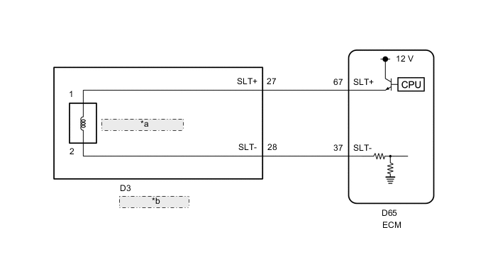
| *a | Solenoid (SLT) Valve |
| *b | Transmission Wire |
CAUTION / NOTICE / HINT
Note
Perform registration and/or initialization when parts related to the automatic transmission are replaced.
PROCEDURE
-
CHECK HARNESS AND CONNECTOR (TRANSMISSION WIRE (SOLENOID (SLT) VALVE) - ECM)
-
Disconnect the ECM connector.
-
Measure the resistance according to the value(s) in the table below.
Standard Resistance Tester Connection Condition Specified Condition D65-67 (SLT+) - D65-37 (SLT-) 20°C (68°F) 5.0 to 5.6 Ω D65-67 (SLT+) or D65-37 (SLT-) - Other terminals Always 10 kΩ or higher Result Proceed to OK NG
NG 
CHECK HARNESS AND CONNECTOR (TRANSMISSION WIRE - ECM) Click here
OK 
-
-
REPLACE ECM
-
Replace the ECM.
Result Proceed to NEXT
NEXT 
PERFORM A/T CODE REGISTRATION Click here
-
-
CHECK HARNESS AND CONNECTOR (TRANSMISSION WIRE - ECM)
-
Disconnect the transmission wire connector.
-
Disconnect the ECM connector.
-
Measure the resistance according to the value(s) in the table below.
Standard Resistance Tester Connection Condition Specified Condition D3-27 (SLT+) or D65-67 (SLT+) - Other terminals Always 10 kΩ or higher D3-28 (SLT-) or D65-37 (SLT-) - Other terminals Always 10 kΩ or higher Result Proceed to OK NG
NG
REPAIR OR REPLACE HARNESS OR CONNECTOR
OK
-
-
INSPECT SOLENOID (SLT) VALVE
-
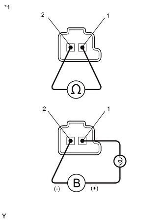
*1 Solenoid (SLT) Valve Remove the solenoid (SLT) valve.
-
Measure the resistance according to the value(s) in the table below.
Standard Resistance Tester Connection Condition Specified Condition 1 - 2 20°C (68°F) 5.0 to 5.6 Ω -
Connect a positive (+) lead from the battery with a 21 W bulb to terminal 1 and a negative (-) lead to terminal 2 of the solenoid valve connector. Check that the valve moves and makes an operating sound.
OK Valve moves and makes an operating sound. Result Proceed to OK NG
OK
REPAIR OR REPLACE TRANSMISSION WIRE Click here
NG
REPLACE SOLENOID (SLT) VALVE Click here
-