ENTRY AND START SYSTEM(for Entry Function) OPERATION CHECK
CHECK ENTRY AND START SYSTEM (for Entry Function) OPERATION
Note:Make sure that the entry and start system (for Entry Function) has not been canceled before performing this inspection.
Check the entry unlock function (driver door, passenger door).
-
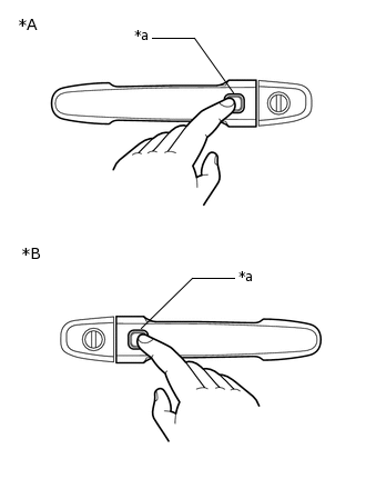
*A
for LHD
*B
for RHD
*a
Trigger Switch
Perform a wireless lock operation to lock the door, press the trigger switch on the front door outside handle assembly (for driver door) of the driver door while carrying the electrical key transmitter sub-assembly and check that the door unlocks.
Tip:To perform a wireless lock operation, press the lock button of the electrical key transmitter sub-assembly while standing near the front door outside handle assembly (for driver door).
-

*A
for LHD
*B
for RHD
*a
0.7 to 1 m (2.30 to 3.28 ft.)
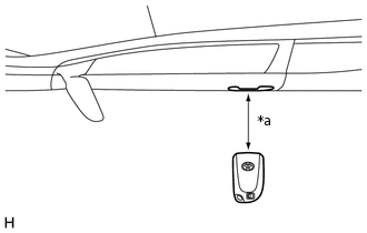
Inspect the entry unlock detection area. Hold the electrical key transmitter sub-assembly at the same height as the front door outside handle assembly (for driver door) and approximately 0.7 to 1 m (2.30 to 3.28 ft.) from the vehicle as shown in the illustration press the trigger switch, and check that all doors unlock.
Tip:Communication may not be possible if the electrical key transmitter sub-assembly is within 0.2 m (0.656 ft.) of the front door outside handle assembly (for diver door).
Inspect the front passenger door using the same procedure.
-
Check the entry lock function (driver door, front passenger door).
Note:If the electrical key transmitter sub-assembly is inside the vehicle but outside the detection area (for example, on top of the instrument panel, on the floor, center LH pillar, in a door pocket or the glove box, or in a storage compartment) and a door lock operation is performed, the key lock-in prevention function will not operate and the electrical key transmitter sub-assembly will be locked inside the vehicle.
-
*A
for LHD
*B
for RHD
*a
Trigger Switch
With the door closed and unlocked, press the trigger switch on the front door outside handle assembly (for driver door) of the driver door while carrying the electrical key transmitter sub-assembly and check that the door locks.
-
*A
for LHD
*B
for RHD
*a
0.7 to 1 m (2.30 to 3.28 ft.)
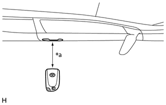
Inspect the entry lock operating range. Hold the electrical key transmitter sub-assembly at the same height as the front door outside handle assembly (for driver door) and approximately 0.7 m to 1 m (2.30 to 3.28 ft.) from the vehicle as shown in the illustration, press the trigger switch, and check that all doors lock.
Tip:If the key lock-in prevention function buzzer sounds, radio waves from an indoor electrical key antenna may be leaking from the vehicle.
Inspect the front passenger door using the same procedure.
-
-
*1
Glass Hatch Opener Switch Assembly
*a
Approximately 0.7 m (2.30 ft.)
Check the entry back door open function.
Perform a wireless lock operation to lock all the doors, operate the glass hatch opener switch assembly while carrying the electrical key transmitter sub-assembly and check that the back door opens.
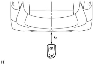
Inspect the entry back door open operating range. While standing at the rear of the vehicle, hold the electrical key transmitter sub-assembly so that it is facing the direction shown in the illustration at the same height as the glass hatch opener switch assembly and approximately 0.7 m (2.30 ft.) from the vehicle, press the glass hatch opener switch assembly and check that the back door opens.
Check the entry back door lock function.
Note:If the electrical key transmitter sub-assembly is inside the vehicle and a door lock operation is performed, it is possible that the electrical key transmitter sub-assembly may be locked inside the vehicle.
With all the doors closed and unlocked, press the lock switch of the glass hatch lock switch assembly while carrying the electrical key transmitter sub-assembly outside of the vehicle and check that all the doors lock.
-
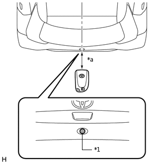
*1
Glass Hatch Lock Switch Assembly
*a
Approximately 0.3 m (0.98 ft.)
Inspect the entry back door lock operating range. Hold the electrical key transmitter sub-assembly so that it is facing the direction shown in the illustration at the same height as the top edge of the rear bumper and approximately 0.3 m (0.98 ft.) from the vehicle, press the glass hatch lock switch assembly and check that all the doors lock.
Tip:Communication may not be possible if the electrical key transmitter sub-assembly is within 0.2 m (0.66 ft.) of the rear bumper.
If the key lock-in prevention function buzzer sounds, radio waves from an indoor electrical key antenna assembly may be leaking from the vehicle.
Check the key lock-in prevention function (vehicle interior).
Note:In order to prevent the electrical key transmitter sub-assembly from being locked inside the vehicle, perform this inspection with the window of a door open.
Turn the engine switch off.
Place the electrical key transmitter sub-assembly on a front or rear seat.
Close the door, making sure the doors are unlocked.
Press the trigger switch on the front door outside handle assembly and check that the doors do not lock and the key lock-in prevention function buzzer (external) sounds for approximately 5 seconds.
Check the push-button start function. (for Multi-Mode Manual Transaxle )
With the engine switch off and the shift lever in N, depress the clutch pedal while carrying the electrical key transmitter sub-assembly and check that the smart warning light in the combination meter assembly illuminates (green). Then, when the smart warning light in the combination meter assembly illuminates (green), press the engine switch and check that the engine starts.
With the clutch pedal released and the engine switch off, press the engine switch while carrying the electrical key transmitter sub-assembly and check that the power source mode changes as follows: off → on (ACC) → on (IG) → off.
When the engine switch is pressed with the engine switch on (IG) and shift lever not in N, the power source mode will not change to off, but to on (ACC).
Stop the vehicle, press the engine switch and check that the power source mode changes to off (the engine stops and all electrical systems are off). When the engine switch is pressed with the shift lever in any position other than N, even if the vehicle is stationary, the power source mode will not change to off, but to on (ACC). Move the shift lever to N, open the door and check that the steering lock operates.
-
*a
Inspection Point
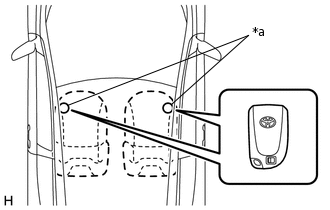
Inspect the push-button start operating range (front floor). Place the electrical key transmitter sub-assembly on the front seat at either inspection point so that it is facing in the direction shown in the illustration and check that the engine can be started.
Note:Even if the electrical key transmitter sub-assembly is within the vehicle interior detection area, the electrical key transmitter sub-assembly may not be properly detected if it is on the instrument panel, in a door pocket, in the glove box, on the floor or in a storage compartment.
Tip:Perform the inspection for both inspection points.
Communication may not be possible if the electrical key transmitter sub-assembly is within 0.2 m (0.656 ft.) of the shift lever.
-
*a
Inspection Point
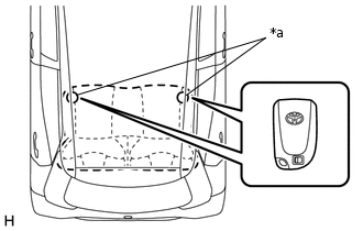
Inspect the push-button start operating range (rear floor). Place the electrical key transmitter sub-assembly on the rear seat at either inspection point so that it is facing in the direction shown in the illustration and check that the engine can be started.
Note:Even if the electrical key transmitter sub-assembly is within the vehicle interior detection area, the electrical key transmitter sub-assembly may not be properly detected if it is on the instrument panel, in a door pocket, in the glove box, on the floor or in a storage compartment.
Tip:Perform the inspection for both inspection points.
Communication may not be possible if the electrical key transmitter sub-assembly is within 0.2 m (0.66 ft.) of the center of the rear seat cushion.
Check the push-button start function. (for Manual Transaxle)
With the engine switch off, depress the clutch pedal while carrying the electrical key transmitter sub-assembly and check that the smart warning light in the combination meter assembly illuminates (green). Then, when the smart warning light in the combination meter assembly illuminates (green), press the engine switch and check that the engine starts.
With the clutch pedal released and the engine switch off, press the engine switch while carrying the electrical key transmitter sub-assembly and check that the power source mode changes as follows: off → on (ACC) → on (IG) → off.
When the engine switch is pressed with the engine switch on (IG), the power source mode will not change to off, but to on (ACC).
-
*a
Inspection Point
Inspect the push-button start operating range (front floor). Place the electrical key transmitter sub-assembly on the front seat at either inspection point so that it is facing in the direction shown in the illustration and check that the engine can be started.
Note:Even if the electrical key transmitter sub-assembly is within the vehicle interior detection area, the electrical key transmitter sub-assembly may not be properly detected if it is on the instrument panel, in a door pocket, in the glove box, on the floor or in a storage compartment.
Tip:Perform the inspection for both inspection points.
Communication may not be possible if the electrical key transmitter sub-assembly is within 0.2 m (0.656 ft.) of the shift lever.
Stop the vehicle, press the engine switch and check that the power source mode changes to off (the engine stops and all electrical systems are off).
-
*a
Inspection Point
Inspect the push-button start operating range (rear floor). Place the electrical key transmitter sub-assembly on the rear seat at either inspection point so that it is facing in the direction shown in the illustration and check that the engine can be started.
Note:Even if the electrical key transmitter sub-assembly is within the vehicle interior detection area, the electrical key transmitter sub-assembly may not be properly detected if it is on the instrument panel, in a door pocket, in the glove box, on the floor or in a storage compartment.
Tip:Perform the inspection for both inspection points.
Communication may not be possible if the electrical key transmitter sub-assembly is within 0.2 m (0.66 ft.) of the center of the rear seat cushion.
Check the transmitter battery saving function
Press the unlock switch of the electrical key transmitter sub-assembly twice while pressing the lock switch and check that the electrical key transmitter sub-assembly LED blinks 4 times and enters transmitter battery saving mode.
Check that the entry and start system (for Entry Function) does not operate while in transmitter battery saving mode.
Tip:To cancel transmitter battery saving mode, press a switch of the electrical key transmitter sub-assembly.
Check the entry cancel function.
Cancel the entry and start system and check that all the functions of the entry and start system (for Entry Function) no longer operate.
Tip:Refer to the following procedures to cancel the entry and start system (for Entry Function).
While the entry and start system is canceled, it is possible to lock and unlock the doors with the wireless function, and the start system can be operated by holding the electrical key transmitter sub-assembly near the engine switch.
Check the answer-back (hazard warning light and wireless buzzer) function
Entry Operation
Hazard Warning Lights
Entry Door Lock
Flash once
Entry Door Unlock
Flash twice
Entry Back Door Lock
Flash once
Entry Back Door Open
Flash twice
KEY DIAGNOSTIC MODE (Using GTS)
Tip:With key diagnostic mode, it is possible to check if an electrical key transmitter sub-assembly is operating properly with the selected electrical key antenna and within the selected detection area by the sounding of the wireless buzzer.
If the buzzer sounds with [CH1] displayed but not with [CH2], the electrical key transmitter sub-assembly cannot be detected by channel 2 due to a malfunction, such as wave interference.
Enter the following menus: Body Electrical / Entry&Start / Utility / Communication Check (Key Diag Mode).
Inspect the appropriate item according to the following table.
Tester Display
Inspection Item
[CH1/CH2] Overhead + Driver Side*1
No. 2 indoor electrical key antenna assembly (center pillar LH)*7
No. 2 indoor electrical key antenna assembly (center pillar RH)*8
[CH1] Overhead + Driver Side*1
[CH2] Overhead + Driver Side*1
[CH1/CH2] Overhead + Passenger Side*2
No. 2 indoor electrical key antenna assembly (center pillar RH)*7
No. 2 indoor electrical key antenna assembly (center pillar LH)*8
[CH1] Overhead + Passenger Side*2
[CH2] Overhead + Passenger Side*2
[CH1/CH2] Overhead + Front Room*3
No. 2 indoor electrical key antenna assembly (center pillar LH) and No. 2 indoor electrical key antenna assembly (center pillar RH)
[CH1] Overhead + Front Room*3
[CH2] Overhead + Front Room*3
[CH1/CH2] Overhead + Back Door*4
No. 3 indoor electrical key antenna assembly (back door)
[CH1] Overhead + Back Door*4
[CH2] Overhead + Back Door*4
[CH1/CH2] Immobiliser Amp*5
Amplifier (engine switch)
[CH1] Immobiliser Amp*5
[CH2] Immobiliser Amp*5
[CH1/CH2] Overhead + Room*6*9
No. 1 indoor electrical key antenna assembly (rear floor)
[CH1] Overhead + Room*6*9
[CH2] Overhead + Room*6*9
[CH1/CH2] Overhead + Room2*7
No. 1 indoor electrical key antenna assembly (front floor)
[CH1] Overhead + Room2*7
[CH2] Overhead + Room2*7
*7: for LHD
*8: for RHD
*9: for 3 Door
Bring the electrical key transmitter sub-assembly near the selected electrical key antenna and check that the wireless door lock buzzer sounds.
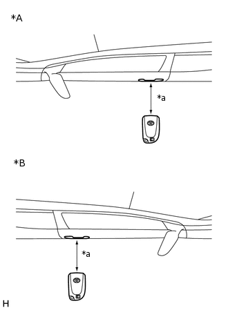
-
*a
0.7 to 1 m (2.30 to 3.28 ft.)
*1: No. 2 indoor electrical key antenna assembly (center pillar LH) (for LHD)
Body Electrical > Entry&Start > Utility
Tester Display
Communication Check(Key Diag Mode)
Tip:Hold the electrical key transmitter sub-assembly at the same height as the front door outside handle assembly (for driver door) in the position shown in the illustration.
*2: Perform the same inspection for the front passenger side.
-
*a
0.7 to 1 m (2.30 to 3.28 ft.)
*1: No. 2 indoor electrical key antenna assembly (center pillar RH) (for RHD)
Body Electrical > Entry&Start > Utility
Tester Display
Communication Check(Key Diag Mode)
Tip:Hold the electrical key transmitter sub-assembly at the same height as the front door outside handle assembly (for driver door) in the position shown in the illustration.
*2: Perform the same inspection for the front passenger side.
-
-
*a
Inspection Point
*3: No. 2 indoor electrical key antenna assembly (center pillar LH) and No. 2 indoor electrical key antenna assembly (center pillar RH)
Body Electrical > Entry&Start > Utility
Tester Display
Communication Check(Key Diag Mode)
Tip:Place the electrical key transmitter sub-assembly on the front seat cushion of the driver seat or front passenger seat.
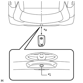
-
*a
Approximately 0.3 m (0.98 ft.)
*4: No. 3 indoor electrical key antenna assembly (back door)
Body Electrical > Entry&Start > Utility
Tester Display
Communication Check(Key Diag Mode)
Tip:Hold the electrical key transmitter sub-assembly at the same height as the rear bumper upper surface and align it with the center of the rear of the vehicle, as shown in the illustration.
-
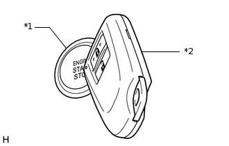
*1
Engine Switch
*2
Electrical Key Transmitter Sub-assembly
*5: Amplifier (engine switch)
Body Electrical > Entry&Start > Utility
Tester Display
Communication Check(Key Diag Mode)
Tip:While facing the logo side of the electrical key transmitter sub-assembly towards the engine switch, hold it the engine switch.
-
*a
Inspection Point
*6: No. 1 indoor electrical key antenna assembly (rear floor) (for 3 Door)
Body Electrical > Entry&Start > Utility
Tester Display
Communication Check(Key Diag Mode)
Tip:Place the electrical key transmitter sub-assembly on the rear seat cushion.
-
*a
Inspection Point
*7: No. 1 indoor electrical key antenna assembly (front floor)
Body Electrical > Entry&Start > Utility
Tester Display
Communication Check(Key Diag Mode)
Tip:Place the electrical key transmitter sub-assembly on the front seat cushion of the driver seat or front passenger seat.