AUDIO AND VISUAL SYSTEM(for Radio Receiver Type) TERMINALS OF ECU
RADIO RECEIVER ASSEMBLY
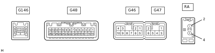
Terminal No. (Symbol)
Wiring Color
Terminal Description
Condition
Specification
G48-4 (MACC) - G46-7 (GND1)
B - BR
Microphone amplifier power supply
Ignition switch off
Below 1 V
Ignition switch ACC
4 to 6 V
G48-5 (MIN+) - G48-19 (MIN-)
W - R
Microphone voice signal
"Bluetooth" hands-free function on
A waveform synchronized with sound is output
G48-6 (SNS2) - G46-7 (GND1)
P - BR
Microphone connection detection signal
Always
Below 1 V
G48-11 (AGND) - Body ground
Shield - Body ground
Shield ground
Always
Below 1 Ω
G48-17 (SPD) - G46-7 (GND1)
BE - BR
Vehicle speed signal
Ignition switch ON Wheel being rotated
Pulse generation
G48-18 (SGND) - Body ground
Shield - Body ground
Shield ground
Always
Below 1 Ω
G48-21 (SW1) - Body ground
W - Body ground
Steering pad switch signal
No switch pushed
2.97 to 3.56 V
Up switch pushed
0.27 to 0.35 V
Down switch pushed
0.86 to 1.03 V
Volume+ switch pushed
1.51 to 1.79 V
Volume- switch pushed
2.22 to 2.66 V
G48-22 (SW2) - Body ground
R - Body ground
Steering pad switch signal
No switch pushed
2.97 to 3.56 V
MODE/HOLD switch pushed
0.27 to 0.35 V
On hook switch pushed
0.86 to 1.03 V
Off hook switch pushed
1.51 to 1.79 V
G48-25 (ADPG) - G46-7 (GND1)
R - BR
External device connection detection signal
External device connected
Below 1 V
G48-26 (VAR+) - G46-7 (GND1)
W - BR
Sound signal (Right)
External device playing (When stereo jack used)
A waveform synchronized with sound is output
G48-27 (VA-) - G46-7 (GND1)
R - BR
Shield ground
Always
Below 1 Ω
G48-28 (VAL+) - G46-7 (GND1)
B - BR
Sound signal (Left)
External device playing (When No. 1 stereo jack adapter assembly used)
A waveform synchronized with sound is output
G46-1 (FR+) - G46-7 (GND1)
LG - BR
Sound signal (Front Right)
Audio system playing
A waveform synchronized with sound is output
G46-2 (FL+) - G46-7 (GND1)
P - BR
Sound signal (Front Left)
Audio system playing
A waveform synchronized with sound is output
G46-3 (ACC1) - G46-7 (GND1)
GR - BR
Power source (ACC)
Ignition switch off
Below 1 V
Ignition switch ACC
11 to 14 V*1
10.5 to 14 V*2
G46-4 (+B1) - G46-7 (GND1)
SB - BR
Power source (+B)
Always
11 to 14 V*1
10.5 to 14 V*2
G46-5 (FR-) - G46-7 (GND1)
L - BR
Sound signal (Front Right)
Audio system playing
A waveform synchronized with sound is output
G46-6 (FL-) - G46-7 (GND1)
V - BR
Sound signal (Front Left)
Audio system playing
A waveform synchronized with sound is output
G46-7 (GND1) - Body ground
BR - Body ground
Ground
Always
Below 1 Ω
G46-10 (ILL+) - G46-7 (GND1)
G - BR
Illumination signal
Light control switch off
Below 1 V
Ignition switch off
Light control switch in tail or head position
11 to 14 V
G47-1 (RR+) - G46-7 (GND1)
R - BR
Sound signal (Rear Right)
Audio system playing
A waveform synchronized with sound is output
G47-2 (RL+) - G46-7 (GND1)
B - BR
Sound signal (Rear Left)
Audio system playing
A waveform synchronized with sound is output
G47-3 (RR-) - G46-7 (GND1)
W - BR
Sound signal (Rear Right)
Audio system playing
A waveform synchronized with sound is output
G47-6 (RL-) - G46-7 (GND1)
Y - BR
Sound signal (Rear Left)
Audio system playing
A waveform synchronized with sound is output
G146-1 (UPO)
#
Power source
-
-
G146-2 (UDO-)
#
Data signal
-
-
G146-3 (UDO+)
#
Data signal
-
-
G146-4 (UESJ)
#
Ground
-
-
RA-5 (ANT+) - G46-7 (GND1)
# - BR
Power source of antenna
Ignition switch ACC Radio switch on and AM or FM selected
11 to 14 V
#: There is no wire color information
*1: w/o Stop and Start System
*2: w/ Stop and Start System