ENGINE ASSEMBLY REMOVAL
-
DISCONNECT CABLE FROM NEGATIVE BATTERY TERMINAL
CAUTION:
Wait at least 90 seconds after disconnecting the cable from the negative (-) battery terminal to prevent airbag and seat belt pretensioner activation.
-
REMOVE FRONT WHEEL
-
REMOVE HOOD SUB-ASSEMBLY
-
Disconnect the washer nozzle hose.
-
Remove the 4 bolts and hood.
-
-
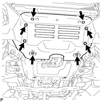
REMOVE NO. 1 ENGINE UNDER COVER (for 4WD)
-
Remove the 8 bolts and under cover.
-
-
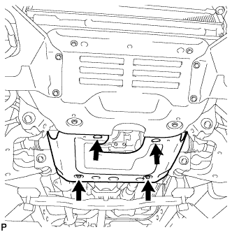
REMOVE NO. 2 ENGINE UNDER COVER (for 4WD)
-
Remove the 4 bolts and under cover.
-
-
LOOSEN FUEL TANK CAP ASSEMBLY
-
DRAIN FUEL
-
DRAIN ENGINE COOLANT
Note
Do not remove the radiator reservoir cap while the engine and radiator are still hot. Pressurized, hot engine coolant and steam may be released and cause serious burns.
-
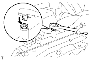
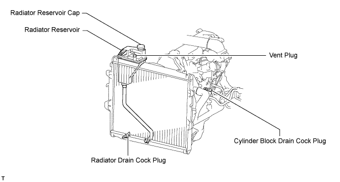
Remove the reservoir cap and, using a wrench, remove the vent plug.
-
Loosen the cylinder block drain cock plug and the radiator drain cock plug and then drain the coolant.
Tech Tips
Collect the coolant in a container and dispose of it according to the regulations in your area.
-
-
DRAIN ENGINE OIL
-
Remove the oil filler cap.
-
Remove the oil drain plug, and drain the oil into a container.
-
Clean the drain plug, and install it with a new gasket.
- Torque:
- 35 N*m { 357 kgf*cm, 26 ft.*lbf }
-
-
REMOVE BATTERY BRACKET
-
Remove the bolt and battery bracket.
-
-
REMOVE BATTERY AND BATTERY TRAY
-
REMOVE AIR CLEANER ASSEMBLY
-
Disconnect the IAT sensor connector.
-
Loosen the air cleaner hose clamp.
-
Remove the 3 bolts and air cleaner.
-
-
DISCONNECT RADIATOR HOSE INLET
-
DISCONNECT RADIATOR HOSE OUTLET
-
REMOVE RADIATOR ASSEMBLY
-
Remove the radiator Click here.
-
-
REMOVE STARTER ASSEMBLY
-
Disconnect the starter connector.
-
Remove the terminal cap.
-
Remove the nut, and disconnect the terminal 30 wire.
-
Remove the nut, 2 bolts and stay.
-
Remove the nut, 2 bolts and starter.
-
-
REMOVE FRONT EXHAUST PIPE ASSEMBLY
-
Remove the 2 bolts from the transmission.
-
Remove the 5 clips and front fender seal LH.
-
Remove the 3 nuts from the exhaust manifold.
-
Disconnect the front exhaust pipe from the exhaust manifold and remove the gasket.
-
Remove the bolt, clamp and pipe support from the front exhaust pipe.
-
-
REMOVE PROPELLER SHAFT ASSEMBLY
-
Front side:
Remove the propeller shaft Click here.
-
Rear side:
Remove the propeller shaft Click here.
-
-
REMOVE TRANSMISSION ASSEMBLY
-
2WD:
Remove the transmission Click here.
-
4WD:
Remove the transmission Click here.
-
-
REMOVE CLUTCH COVER ASSEMBLY
-
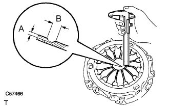
Using a vernier caliper, measure the depth and width of the worn areas of the diaphragm spring.
Maximum depth and width Measurement Specified Condition A (Depth) 0.5 mm (0.020 in.) B (Width) 6.0 mm (0.236 in.) If the depth or width is greater than the maximum, replace the clutch cover assembly.
-
-
REMOVE CLUTCH DISC ASSEMBLY
Note
Keep the lining part of the clutch disc, pressure plate and surface of the flywheel away from oil and foreign matter.
-
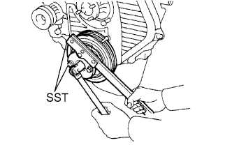
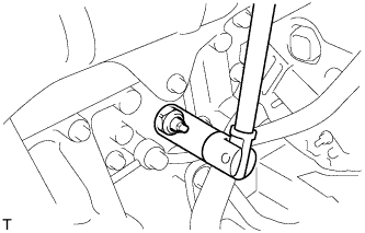
REMOVE FLYWHEEL SUB-ASSEMBLY
-
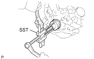
Using SST, hold the crankshaft.
- SST
- 09213-54015 ( 91651-60855 )
- 09330-00021
-
Remove the 8 bolts and flywheel.
-
-
REMOVE REAR END PLATE
-
Remove the 2 bolts and rear end plate.
-
-
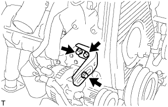
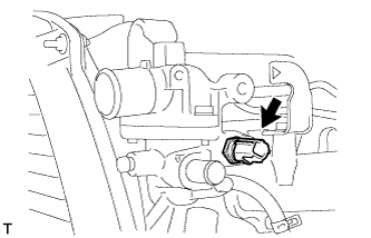
DISCONNECT HOSES AND CONNECTORS
-
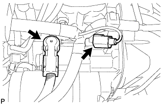
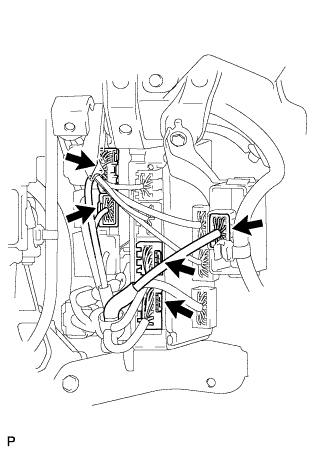
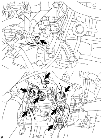
4WD:
Disconnect the connector and clamp as shown in the illustration.
-
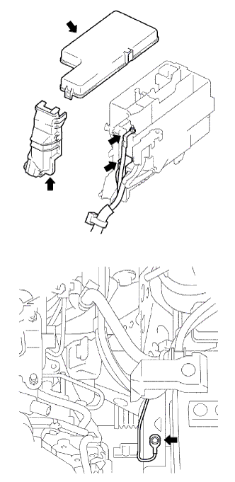
Remove the engine room relay block cover (upper).
-
Remove the No. 1 engine room relay block cover (side).
-
Remove the nut and disconnect the engine room junction block wire.
-
Disconnect the 2 engine room junction block connectors.
-
Remove the bolt and disconnect the ground cable.
-
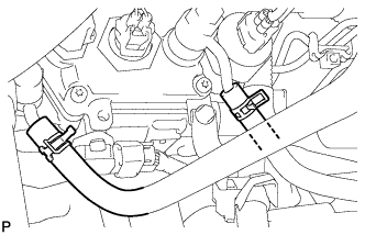
Disconnect the 2 fuel hoses.
-
Disconnect the 2 water hoses.
-
Remove the water hose clamp bolt.
-
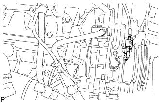
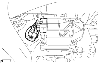
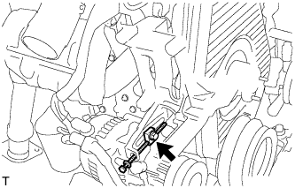
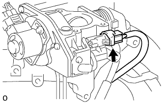
Disconnect the compressor connector.
-
Disconnect the connectors as shown in the illustration.
-
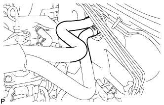
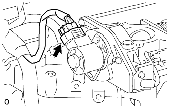
Disconnect the vacuum pump hose from the generator.
-
-
DISCONNECT COMPRESSOR AND MEGNET CLUTCH (w/ Air Conditioning System)
-
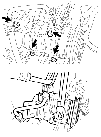
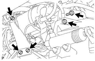
Remove the 4 bolts and disconnect the cooler compressor.
Tech Tips
It is not necessary to completely remove the compressor. With the hoses connected to the compressor, hang the compressor on the vehicle body with a rope.
-
-
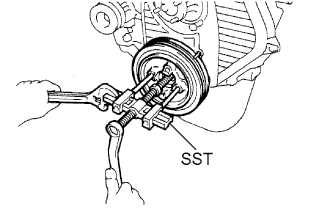
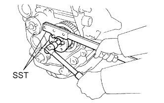
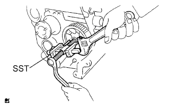
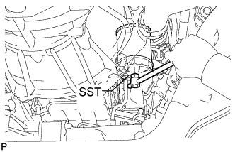
DISCONNECT VANE PUMP ASSEMBLY
-
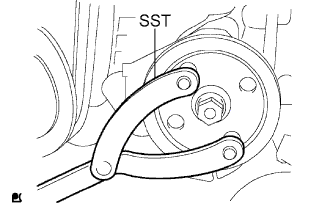
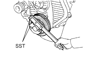
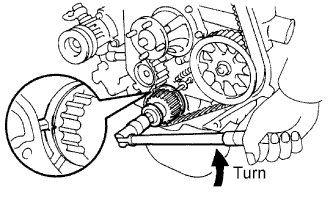
Using SST, stop the pulley rotation and loosen the nut.
- SST
- 09960-10010 ( 09962-01000, 09963-01000 )
-
Remove the nut and vane pump pulley from the vane pump shaft.
-
Remove the 2 bolts and nut, and disconnect the vane pump.
Tech Tips
Disconnect the vane pump with the hoses connected, and it should be hung with a rope.
-
-
INSTALL NO. 2 ENGINE HANGER
-
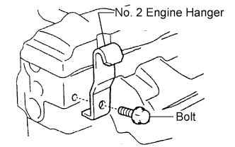
Set the No. 2 engine hanger to the location shown in the illustration.
- Torque:
- 37 N*m { 380 kgf*cm, 27 ft.*lbf }
Engine hanger part No.: Parts Name Parts No. Engine hanger No .2 12282-54060 Bolt 91622-61022 Note
Install the engine hangers with new bolts.
-
-
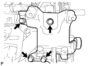
REMOVE ENGINE ASSEMBLY
-
Hold the engine with the engine sling device and chain block.
-
Remove the 4 bolts and 4 nuts.
-
Remove the engine by operating the engine sling device and chain block.
-
-
FIX ENGINE ON ENGINE STAND
-
REMOVE ENGINE WIRE
-
Remove the engine wire from the engine assembly.
-
-
REMOVE FAN BELT ADJUSTING BAR (w/o Air Conditioning System)
-
Remove the 3 bolts and fan belt adjusting bar.
-
-
REMOVE COMPRESSOR MOUNTING BRACKET (w/ Air Conditioning System)
-
Remove the bolt and spacer.
-
Remove the 4 bolts and compressor mounting bracket.
-
-
REMOVE CRANKSHAFT PULLEY
-
Using SST, remove the pulley bolt.
- SST
- 09213-54015 ( 91651-60855 )
- 09330-00021
-
Using SST, remove the pulley.
- SST
- 09950-50013 ( 09951-05010, 09952-05010, 09953-05020, 09954-05021 )
- 09950-60010 ( 09951-00490 )
- 09950-40011 ( 09957-04010 )
-
-
REMOVE TIMING BELT COVER SUB-ASSEMBLY
-
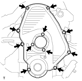
Remove the 11 bolts, washers, timing belt cover and 2 gaskets.
-
-
REMOVE TIMING BELT
-
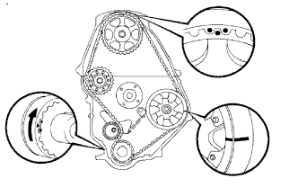
Remove the timing belt.
Tech Tips
If reusing the timing belt, draw a direction arrow on the timing belt (in the direction of engine revolution), and place matchmarks on the pulleys and timing belt.
-
Turn the crankshaft 90° counterclockwise, and put the timing mark of the crankshaft timing pulley with the protrusion of the timing gear case.
Note
If the timing belt is disengaged, having the crankshaft timing pulley at the wrong angle can cause the piston head and valve head to come into contact with each other when you remove the camshaft timing pulley, causing damage. So always set the crankshaft pulley at the correct angle.
-
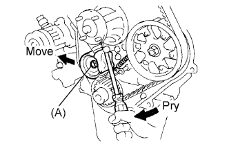
Loosen the No. 1 timing belt idler bolt (A), and shift the idler to the left as far as possible.
-
Temporarily tighten the pulley bolt (A), and then relieve the timing belt tension.
-
Remove the timing belt.
-
-
REMOVE CRANKSHAFT TIMING PULLEY
-
Using SST, remove the timing pulley.
- SST
- 09950-50013 ( 09951-05010, 09952-05010, 09953-05010, 09953-05020, 09954-05010 )
-
-
REMOVE INTAKE PIPE ASSEMBLY
-
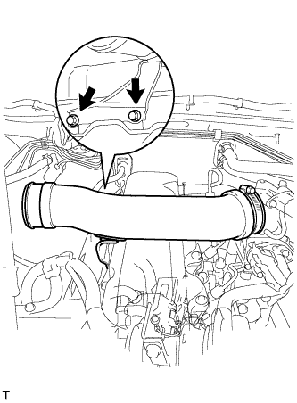
Loosen the intake pipe clamp.
-
Remove the 2 bolts and intake pipe.
-
-
REMOVE VENTURI ASSEMBLY
-
Disconnect the throttle open switch connector.
-
Disconnect the throttle control motor connector.
-
Remove the venturi and gasket.
-
-
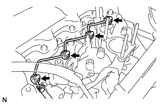
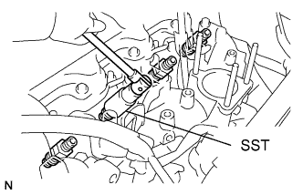
REMOVE INJECTION PIPE SET
-
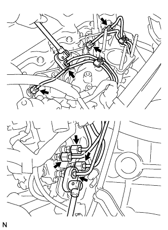
Using a union nut wrench, loosen the 8 union nuts of the 4 injection pipes.
-
Remove the 2 nuts, 2 upper pipe clamps and 4 injection pipes with lower pipe clamps.
-
-
REMOVE NO. 1 GLOW PLUG CONNECTOR
-
Remove the nut and wire harness.
-
Remove the 4 screw grommets, 4 nuts and glow plug connector.
-
-
REMOVE NOZZLE LEAKAGE PIPE ASSEMBLY
-
Disconnect the fuel hose from the leakage pipe.
-
Remove the 4 nuts, leakage pipe and 4 ring packing washers.
-
-
REMOVE NOZZLE HOLDER & NOZZLE SET
-
Using SST, remove the 4 injection nozzles, 4 injection nozzle seats and 4 injection nozzle seat gaskets.
- SST
- 09268-64010 ( 09268-64020 )
-
-
REMOVE GLOW PLUG ASSEMBLY
-
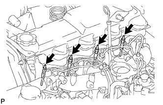
Using a 12 mm deep socket wrench, remove the 4 glow plugs.
-
-
REMOVE INJECTION PUMP DRIVE PULLEY
-
Using SST, remove the pulley nut.
- SST
- 09213-14010 ( 91651-60865 )
- 09330-00021
-
Using SST, remove the drive pulley.
- SST
- 09950-50013 ( 09951-05010, 09952-05010, 09953-05010, 09954-05021 )
-
-
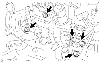
REMOVE INJECTION PUMP ASSEMBLY
-
Disconnect the engine speed sensor connector.
-
Disconnect the spill control valve connector.
-
Disconnect the correction unit connector.
-
Disconnect the timing control valve connector.
-
Disconnect the fuel temperature sensor connector.
-
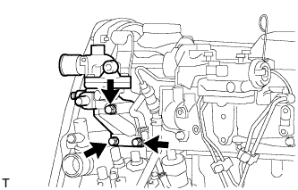
Disconnect the engine wire clamp.
-
Disconnect the 3 fuel hoses.
-
Remove the 3 bolts and injection pump stay.
-
Remove the 2 nuts and injection pump.
-
-
REMOVE CRANKSHAFT POSITION SENSOR
-
Remove the bolt, sensor and O-ring.
-
-
REMOVE ENGINE COOLANT TEMPERATURE SENSOR
-
Using a 17 mm deep socket wrench, remove the sensor.
-
-
REMOVE WATER OUTLET HOUSING
-
Remove the 3 bolts, outlet housing and gasket.
-
-
REMOVE INTAKE MANIFOLD
-
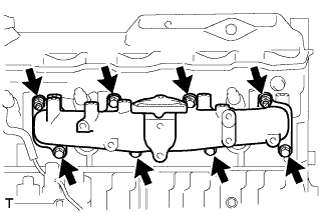
Remove the 6 bolts, 2 nuts, intake manifold and gasket.
-
-
REMOVE WATER BY-PASS HOSE UNION
-
Remove the water by-pass hose union.
-
-
REMOVE CYLINDER BLOCK WATER DRAIN COCK SUB-ASSEMBLY
-
Remove the cylinder block water drain cock sub-assembly.
-
-
REMOVE PUMP BRACKET
-
Remove the 6 bolts and pump bracket.
-
-
REMOVE GENERATOR ASSEMBLY
-
Remove the generator assembly Click here.
-
-
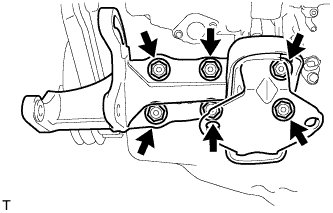
REMOVE NO. 1 FRONT ENGINE MOUNTING BRACKET RH
-
Remove the 4 bolts and engine mounting bracket.
-
-
REMOVE OIL DIPSTICK SUB-ASSEMBLY
-
REMOVE OIL DIPSTICK GUIDE
-
Remove the 2 bolts, guide and O-ring.
-
-
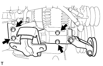
REMOVE NO. 1 EXHAUST MANIFOLD HEAT INSULATOR
-
Remove the 3 bolts and heat insulator.
-
-
REMOVE EXHAUST MANIFOLD
-
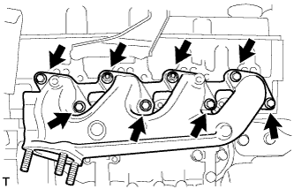
Remove the 6 bolts, 2 nuts and manifold.
-
Remove the manifold gasket from the cylinder head.
-
-
REMOVE OIL FILTER SUB-ASSEMBLY
-
Using SST, remove the oil filter.
- SST
- 09228-44011
-
-
REMOVE OIL FILTER BRACKET SUB-ASSEMBLY
-
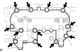
Remove the 10 bolts, 2 nuts, oil filter bracket and gasket.
-
-
REMOVE ENGINE OIL PRESSURE SWITCH ASSEMBLY
-
Using a 24 mm deep socket wrench, remove the oil pressure switch.
-
-
REMOVE WIRE HARNESS CLAMP BRACKET
-
Remove the bolt and wire harness clamp bracket.
-