REAR POWER SEAT CONTROL SYSTEM Power Source Circuit
| DTC Code | DTC Name |
|---|---|
| Power Source Circuit |
DESCRIPTION
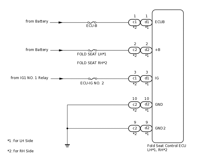
Power is supplied to the fold seat control ECU through the ECU-B, FOLD SEAT LH*1, FOLD SEAT RH*2 and ECU-IG NO. 2 fuses.
*1: for LH Side
*2: for RH Side
WIRING DIAGRAM
CAUTION / NOTICE / HINT
Inspect the fuses for circuits related to this system before performing the following inspection procedure.
PROCEDURE
CHECK HARNESS AND CONNECTOR (FOLD SEAT CONTROL ECU - BATTERY AND BODY GROUND)
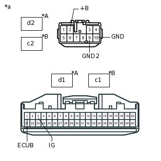
*A
for LH Side
*B
for RH Side
*a
Front view of wire harness connector (to Fold Seat Control ECU)
for LH Side:
Disconnect the d1 and d2 ECU connectors.
for RH Side:
Disconnect the c1 and c2 ECU connectors.
Measure the voltage according to the value(s) in the table below.
Standard Voltage
Table 1. for LH Side Tester Connection
Condition
Specified Condition
d2-2 (+B) - Body ground
Always
11 to 14 V
d1-1 (ECUB) - Body ground
Always
11 to 14 V
d1-3 (IG) - Body ground
Engine switch off
Below 1 V
Engine switch on (IG)
11 to 14 V
Table 2. for RH Side Tester Connection
Condition
Specified Condition
c2-2 (+B) - Body ground
Always
11 to 14 V
c1-1 (ECUB) - Body ground
Always
11 to 14 V
c1-3 (IG) - Body ground
Engine switch off
Below 1 V
Engine switch on (IG)
11 to 14 V
Measure the resistance according to the value(s) in the table below.
Standard Resistance
Table 3. for LH Side Tester Connection
Condition
Specified Condition
d2-10 (GND) - Body ground
Always
Below 1 Ω
d2-9 (GND2) - Body ground
Always
Below 1 Ω
Table 4. for RH Side Tester Connection
Condition
Specified Condition
c2-10 (GND) - Body ground
Always
Below 1 Ω
c2-9 (GND2) - Body ground
Always
Below 1 Ω
Result
Result
OK
NG
NG REPAIR OR REPLACE HARNESS OR CONNECTOR