SLIDING ROOF HOUSING(for Sliding roof) REASSEMBLY
PROCEDURE
-
INSTALL ROOF WIND DEFLECTOR PANEL SUB-ASSEMBLY
-
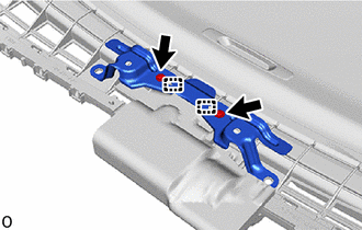
Attach the claw as shown in the illustration to install the roof wind deflector panel sub-assembly in the direction indicated by the arrow (1) shown in the illustration.
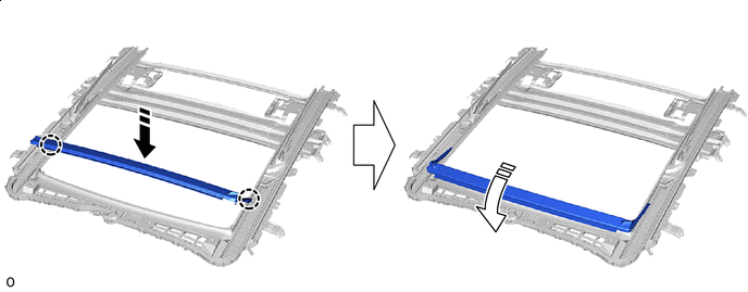

Install in this Direction (1) 
Hold in this Direction (2) -
Hold down in the direction indicated by the arrow (2) shown in the illustration.
-
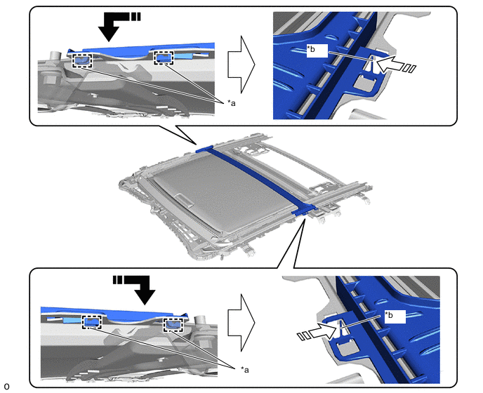
Attach the springs to the guides of the roof wind deflector panel sub-assembly shown in the illustration.
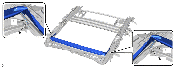
*a Spring *b Guide -
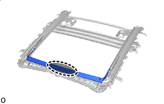

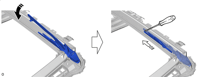
Hold Position Hold the roof wind deflector panel sub-assembly until the sliding roof drive cable sub-assembly goes over the roof wind deflector panel sub-assembly.
-
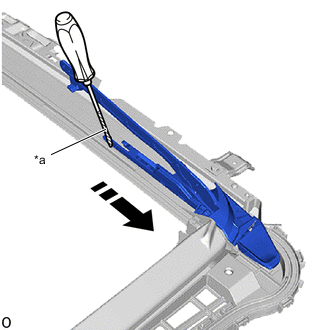
*a Protective Tape Slide in this Direction Using a screwdriver, slide the roof wind deflector panel sub-assembly as shown in the illustration.
Tech Tips
-
Tape the screwdriver tip before use.
-
Use the same procedure for the RH side.
-
-
Lock the roof wind deflector panel sub-assembly as shown in the illustration and slide it.
Lock Slide in this Direction
-
-
INSTALL SUNSHADE TRIM SUB-ASSEMBLY
-
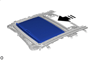
Install in this Direction Insert the sunshade trim sub-assembly as shown in the illustration.
-
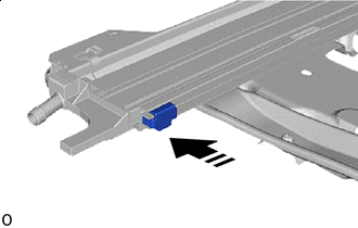
Install in this Direction Install the rear sliding roof sunshade stopper as shown in the illustration.
Tech Tips
Use the same procedure for the RH side.
-
Attach the guide in the direction indicated by the arrow (1) shown in the illustration.
*a Claw *b Guide Install in this Direction (1) Install in this Direction (2) -
Attach the claw in the direction indicated by the arrow (2) shown in the illustration to install the sliding roof channel.
-
-
INSTALL SLIDING ROOF DRIVE GEAR SUB-ASSEMBLY
-
When reusing sliding roof drive gear sub-assembly:
-
Remove any remaining double-sided tape from the sliding roof drive gear sub-assembly.
-
-
Apply MP grease to the gear of the sliding roof drive gear sub-assembly.
-
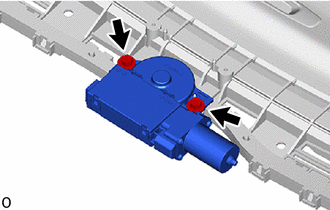
Temporarily install the sliding roof drive gear sub-assembly with the 2 bolts.
-
Tighten the 2 bolts.
Note
While balancing the bolt upright, tighten it evenly.
- Torque:
- 5.4 N*m { 55 kgf*cm, 48 in.*lbf }
-
-
INSTALL SLIDING ROOF HOUSING PAD
-
Install a new sliding roof housing pad as shown in the illustration.
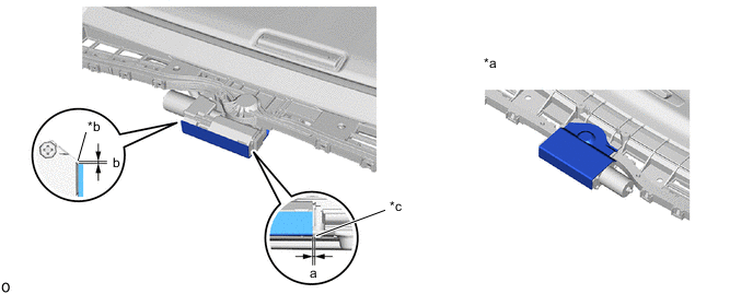
*a Backside *b R End *c Sliding Roof Drive Gear Sub-assembly End (Application Standard Point) - - Standard Location Measurement a 0 to 3 mm (0 to 0.118 in.) b -1.5 to 1.5 mm (-0.0591 to 0.0591 in.)
-
-
INSTALL NO. 2 SLIDING ROOF HOUSING PAD
-
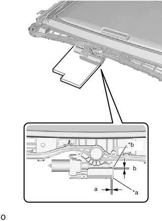
*a Sliding Roof Drive Gear Sub-assembly End (Application Standard Point) *b Sliding Roof Drive Gear Sub-assembly Stepped Edge (Application Standard Point) Install a new No. 2 sliding roof housing pad as shown in the illustration.
Standard Location Measurement a 0 to 3 mm (0 to 0.118 in.) b -3 to 0 mm (-0.118 to 0 in.) -
Paste the No. 2 sliding roof housing pad as shown in the illustration.
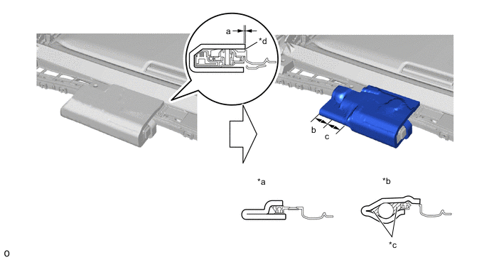
*a Cross-section of part b *b Cross-section of part c *c Gaps in the hatched area are allowed *d R End (Application Standard Point) Standard Location Measurement a 0 to 3 mm (0 to 0.118 in.) b 31.2 mm (1.23 in.) c 40 mm (1.57 in.) -
Attach the guide.
-
Install the map light bracket with the 2 screws.
- Torque:
- 1.1 N*m { 11 kgf*cm, 10 in.*lbf }
-