СИСТЕМА SFI, Diagnostic DTC:P0300, P0301, P0302, P0303, P0304
| DTC Code | DTC Name |
|---|---|
| P0300 | Random / Multiple Cylinder Misfire Detected |
| P0301 | Cylinder 1 Misfire Detected |
| P0302 | Cylinder 2 Misfire Detected |
| P0303 | Cylinder 3 Misfire Detected |
| P0304 | Cylinder 4 Misfire Detected |
DESCRIPTION
When a misfire occurs in the engine, hydrocarbons (HC) enter the exhaust gas in high concentrations. If this HC concentration is high enough, there could be an increase in exhaust emission levels. High concentrations of HC can also cause the temperature of the catalyst to increase, possibly damaging the catalyst. To prevent this increase in emissions and limit the possibility of thermal damage, the ECM monitors the misfire rate.
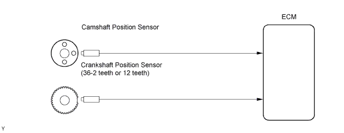
When the temperature of the catalyst reaches a point of thermal degradation, the ECM will start blinking the MIL. For monitor misfire, the ECM uses both the camshaft position sensor and the crankshaft position sensor.
The camshaft position sensor is used to identify if misfiring cylinders and the crankshaft position sensor is used to measure variations in the crankshaft rotation speed. The misfire counter increases when crankshaft rotation speed variations exceed the threshold values.
If the misfiring rate exceeds the threshold and could cause emission deterioration, the ECM illuminates the MIL.
Tech Tips
-
For any 200 revolutions of the engine, if misfiring which could result in overheating of the catalyst is detected, the MIL will start blinking (1 trip detection logic).
-
For any 1,000 revolutions of the engine, if misfiring which could result in emission deterioration is detected, the MIL will illuminate (2 trip detection logic).
| DTC No. | DTC Detection Condition | Trouble Area |
|---|---|---|
| P0300 | Misfiring of random cylinders is detected |
|
| P0301 P0302 P0303 P0304 |
Misfiring of each cylinder is detected |
|
Tech Tips
When the DTCs for misfiring cylinders are recorded repeatedly but no random misfire DTC is recorded, it indicates that the misfires have been set and recorded at different times.
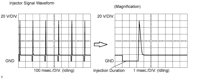
Reference: Inspect using the oscilloscope
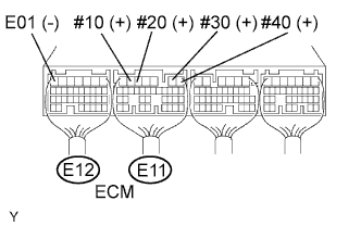
With the engine idling, check the waveform between terminals #10 to #40 and E01 of the ECM connectors.
| Tool Setting | Condition |
|---|---|
| 20 V / DIV., 100 or 1 msec. / DIV. | Idling |
Tech Tips
The correct waveform is as shown.
MONITOR DESCRIPTION
The ECM illuminates the MIL (2 trip detection logic) if:
-
The misfiring rate exceeds a threshold value and could cause emissions deterioration.
-
During the first 1,000 engine revolutions after the engine starts, an excessive misfire rate (approximately 20 to 50 misfires per 1,000 engine revolutions) occurs 1 time.
-
After the first 1,000 engine revolutions after the engine starts, an excessive misfire rate (approximately 20 to 50 misfires per 1,000 engine revolutions) occurs 4 times.
The ECM blinks the MIL (MIL blinks immediately) if:
-
Within 200 engine revolutions at a high rpm, the threshold for "percent of misfire causing catalyst damage" is reached 1 time.
-
Within 200 engine revolutions at a normal rpm, the threshold for "percent of misfire causing catalyst damage" is reached 3 times. (for the 2nd trip, reaching the threshold once will cause the MIL to blink).
CONFIRMATION DRIVING PATTERN
-
Connect the intelligent tester to the DLC3.
-
Turn the ignition switch ON and turn the intelligent tester ON.
-
Note the DTC(s) and freeze frame data.
-
Change the ECM from normal mode to check mode using the intelligent tester.
-
Check the misfire counter values for each cylinder when idling. If the misfire counter indicates 0, perform the following confirmation driving pattern procedure.
-
Drive the vehicle several times using the engine speed data (Engine Speed), engine load data (Calculate Load) and other data stored in the freeze frame data.
-
If you are not using the intelligent tester, turn the ignition switch OFF after the symptom is simulated once. Then repeat the simulation process again.
Tech Tips
In order to memorize the misfire DTCs, it is necessary to drive around with Misfire RPM and Misfire Load selected in the Data List for the following period of time. Do not turn the ignition switch OFF. Turning the ignition switch OFF changes the diagnosis system from check mode to normal mode, and all DTCs and freeze frame data will be erased.
Engine Speed Time Idling 3 minutes 30 seconds or more 1,000 rpm 3 minutes or more 2,000 rpm 1 minute 30 seconds or more 3,000 rpm 1 minute or more -
Check for DTCs to verify whether misfires have occurred. If DTCs are present, record the DTC and freeze frame data.
-
Turn the ignition switch OFF and wait for at least 5 seconds.
INSPECTION PROCEDURE
Tech Tips
-
If DTCs besides the misfire DTCs are set simultaneously, first perform troubleshooting for them.
-
If a misfire does not occur when the vehicle is brought to the workshop, a misfire can be confirmed by reproducing the condition of the freeze frame data. Also, after finishing repairs, confirm that misfires do not recur (see the confirmation driving pattern).
-
Read freeze frame data using the intelligent tester. Freeze frame data records the engine conditions when malfunctions are detected. When troubleshooting, freeze frame data can help determine if the vehicle was moving or stationary, if the engine was warmed up or not, if the air-fuel ratio was lean or rich, and other data from the time the malfunction occurred.
-
When only a general misfire DTC P0300 is stored:
-
Erase the general misfire DTC from the ECM using the intelligent tester.
-
Start the engine and perform the confirmation driving pattern.
-
Check the value of the misfire ratio for each cylinder or check for DTC(s).
-
Perform repairs on the cylinder that has a high misfire ratio or on the cylinder indicated by the DTC.
-
After finishing repairs, perform the confirmation driving pattern again and confirm that no misfire occurs.
-
When either Short FT #1 or Long FT #1 in the freeze frame data is over the range of +- 20%, there is a possibility that the air-fuel ratio is becoming rich (-20% or less) or lean (+20% or more).
-
When the Coolant Temp value in the freeze frame data is less than 80°C (176°F), there is a possibility that misfires occur only during engine warm-up.
-
If a misfire cannot be reproduced, the following reasons may apply: 1) the vehicle has low fuel, 2) improper fuel is being used, and 3) the ignition plug has been contaminated.
-
Be sure to check the misfire counter value after repairs.
PROCEDURE
-
CHECK OTHER DTC OUTPUT (IN ADDITION TO MISFIRE DTCS)
-
Connect the intelligent tester to the DLC3.
-
Turn the ignition switch ON.
-
Turn the tester ON.
-
On the tester, select the following menu items: Powertrain / Engine and ECT / DTC.
-
Read DTCs.
Result Display (DTC Output) Proceed to One or more of P0300, P0301, P0302, P0303 and P0304 A One or more of P0300, P0301, P0302, P0303 and P0304, and other DTCs B Tech Tips
If any DTCs other than P0300, P0301, P0302, P0303 and P0304 are output, troubleshoot those DTCs first.
B 
GO TO RELEVANT DTC CHART
A 
-
-
READ VALUE USING DATA LIST (MISFIRE RPM, MISFIRE LOAD)
-
Connect the intelligent tester to the DLC3.
-
Turn the ignition switch ON and turn the tester ON.
-
Select the following menu items: Powertrain / Engine and ECT / Data List / Misfire RPM and Misfire Load.
-
Read and note the Misfire RPM and Misfire Load (engine load) values.
Tech Tips
The Misfire RPM and Misfire Load indicate the vehicle conditions under which the misfire occurred.
NEXT
-
-
CHECK PCV HOSE
OK PCV hose is connected correctly, and is not damaged.
NG
REPAIR OR REPLACE PCV HOSE
OK
-
CHECK MISFIRE COUNT (CYL #1, #2, #3, #4)
(a) Connect the intelligent tester to the DLC3.
(b) Turn the ignition switch ON.
(c) Turn the tester ON.
(d) Clear DTCs.
(e) On the tester, select the following menu items: Powertrain / Engine and ECT / Data List / CYL #1, #2, #3 and #4.
(f) Allow the engine to idle.
(g) Read each value of CYL #1 to #4 displayed on the tester. If no misfire counts occur in any cylinders, perform the following operations:
-
(1) Move the shift lever to the drive position.
-
(2) Repeat steps (e) to (g) above.
-
(3) Check the CYL #1 to #4.
-
(4) If misfire counts are still not displayed, perform steps (h) and (i) and then check the misfire counts again.
(h) Drive the vehicle at the Misfire RPM and Misfire Load values recorded from the Data List.
(i) Read the CYL #1 to #4 or DTCs displayed on the tester.
Result Misfire Count Proceed to One or two cylinders have misfire counts A Three cylinders or more have misfire counts B
B 
CHECK AIR INDUCTION SYSTEM Click here
A
-
-
CHECK SPARK PLUG
-
Remove the ignition coil assembly.
-
Remove the spark plug.
-
Check the spark plug type.
Recommended spark plug: Supplier Type DENSO K20HR-U11 -
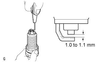
Check the spark plug electrode gap.
Correct electrode gap for new spark plug 1.0 to 1.1 mm (0.039 to 0.043 in.) Maximum electrode gap for used spark plug 1.33 mm (0.0532 in.) Note
If adjusting the gap of a new spark plug, only bend the ground electrode. Do not touch the tip. Never attempt to adjust the gap of a used plug.
-
Check the electrode for carbon deposits.
NG
REPLACE SPARK PLUG
OK
-
-
CHECK FOR SPARKS AND IGNITION
-
Perform a spark test.
CAUTION:
Make sure to disconnect each injector connector.
Note
Do not crank the engine for more than 5 seconds.
-
Install the spark plug to the ignition coil, and connect the ignition coil connector.
-
Disconnect the injector connector.
-
Ground the spark plug.
-
Check if sparks occur while the engine is being cranked.
OK Sparks jump across electrode gap.
-
NG
CHANGE NORMAL SPARK PLUG AND CHECK SPARK OF MISFIRING CYLINDER Click here
OK
-
-
CHECK CYLINDER COMPRESSION PRESSURE OF MISFIRING CYLINDER
-
Measure the cylinder compression pressure of the misfiring cylinder Click here.
OK
INSPECT ECM TERMINAL OF MISFIRING CYLINDER (#10, #20, #30, #40 VOLTAGE) Click here
NG 
CHECK ENGINE TO DETERMINE CAUSE OF LOW COMPRESSION
-
-
CHANGE NORMAL SPARK PLUG AND CHECK SPARK OF MISFIRING CYLINDER
-
Change the installed spark plug to a spark plug that functions normally.
-
Perform a spark test.
CAUTION:
Make sure to disconnect each injector connector.
Note
Do not crank the engine for more than 5 seconds.
-
Install the spark plug to the ignition coil, and connect the ignition coil connector.
-
Disconnect the injector connector.
-
Ground the spark plug.
-
Check if sparks occur while the engine is being cranked.
OK Sparks jump across electrode gap.
-
NG
REPLACE IGNITION COIL ASSEMBLY THEN CONFIRM THAT THERE IS NO MISFIRE
OK
REPLACE SPARK PLUG
-
-
INSPECT ECM TERMINAL OF MISFIRING CYLINDER (#10, #20, #30, #40 VOLTAGE)
-
Turn the ignition switch ON.
-
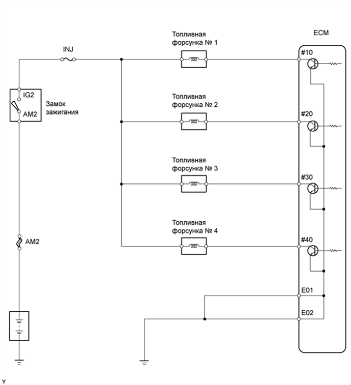
Measure the voltage of the E11 and E12 ECM connectors.
Standard voltage Tester Connection Specified Condition E11-6 (#10) - E12-7 (E01) 9 to 14 V E11-5 (#20) - E12-7 (E01) 9 to 14 V E11-2 (#30) - E12-7 (E01) 9 to 14 V E11-1 (#40) - E12-7 (E01) 9 to 14 V
OK
CHECK FUEL INJECTOR OF MISFIRING CYLINDER Click here
NG
-
-
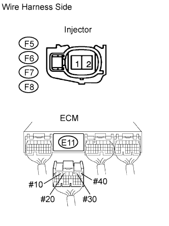
CHECK WIRE HARNESS (INJECTOR - ECM)
-
Check the wire harness between the injector and ECM.
-
Disconnect the F5, F6, F7 and F8 injector connectors.
-
Disconnect the E11 connector.
-
Measure the resistance of the wire harness side connectors.
Standard resistance Tester Connection Specified Condition F5-2 - E11-6 (#10) Below 1 Ω F6-2 - E11-5 (#20) Below 1 Ω F7-2 - E11-2 (#30) Below 1 Ω F8-2 - E11-1 (#40) Below 1 Ω F5-2 or E11-6 (#10) - Body ground 10 kΩ or higher F6-2 or E11-5 (#20) - Body ground 10 kΩ or higher F7-2 or E11-2 (#30) - Body ground 10 kΩ or higher F8-2 or E11-1 (#40) - Body ground 10 kΩ or higher
-
-
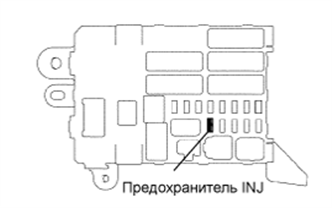
Inspect the INJ fuse.
-
Remove the INJ fuse from the instrument panel junction block.
-
Measure the resistance of the INJ fuse.
Standard resistance Below 1 Ω
-
-
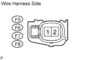
Measure the voltage of the injector connectors.
-
Disconnect the F5, F6, F7 and F8 injector connectors.
-
Turn the ignition switch ON.
-
Measure the voltage of the wire harness side connectors.
Standard voltage Tester Connection Specified Condition F5-1 - Body ground Between 11 and 14 V F6-1 - Body ground Between 11 and 14 V F7-1 - Body ground Between 11 and 14 V F8-1 - Body ground Between 11 and 14 V
-
NG
REPAIR OR REPLACE HARNESS AND CONNECTOR
OK
-
-
CHECK FUEL INJECTOR OF MISFIRING CYLINDER
-
Check the injector injection. Check that fuel volume is not too high or too low, and that the injection pattern is not poor Click here.
NG
REPLACE FUEL INJECTOR ASSEMBLY
OK
-
-
CHECK AIR INDUCTION SYSTEM
-
Check the air induction system for vacuum leakage.
OK No leakage from air induction system.
NG
REPAIR OR REPLACE AIR INDUCTION SYSTEM
OK
-
-
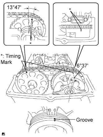
CHECK VALVE TIMING
-
Remove the cylinder head cover.
-
Turn the crankshaft to align the timing marks of the crankshaft.
-
Align the groove of the crankshaft pulley with the "0" position.
-
Confirm whether the timing marks of the camshaft pulley and cylinder head cover are facing each other.
-
If the timing marks are not facing each other, turn the crankshaft clockwise by 360°. Confirm again if the timing marks are facing each other.
OK The timing marks of the camshaft pulley and the cylinder head cover face each other when the groove of the crankshaft pulley is in the "0" position.
NG
ADJUST VALVE TIMING
OK
-
-
CHECK FUEL PRESSURE
-
Check the fuel pressure Click here.
NG
CHECK AND REPLACE FUEL PUMP, PRESSURE REGULATOR, FUEL PIPE LINE AND FILTER
OK
-
-
READ VALUE USING DATA LIST (COOLANT TEMP)
-
Connect the intelligent tester to the DLC3.
-
Turn the ignition switch ON.
-
Turn the tester ON.
-
On the tester, select the following menu items: Powertrain / Engine and ECT / Data List / Coolant Temp.
-
Read the Coolant Temp value twice, when the engine is both cold and warmed up.
Standard With cold engine: Same as ambient air temperature With warm engine: Between 75 and 95°C (167 and 203°F)
NG
REPLACE ENGINE COOLANT TEMPERATURE SENSOR
OK
-
-
READ VALUE USING DATA LIST (MAF)
-
Connect the intelligent tester to the DLC3.
-
Turn the ignition switch ON.
-
Turn the tester ON.
-
On the tester, select the following menu items: Powertrain / Engine and ECT / Data List / MAF and Coolant Temp.
-
Allow the engine to idle until the Coolant Temp value reaches 75°C (167°F) or more.
-
Read the MAF with the engine in an idling condition and at an engine speed of 2,500 rpm.
Standard MAF while engine idling: Between 1 and 4 g/sec. (shift position: neutral; A/C: OFF). MAF at engine speed of 2,500 rpm: Between 4 and 15 g/sec. (shift position: neutral; A/C: OFF).
NG
REPLACE MASS AIR FLOW METER
OK
CHECK FOR INTERMITTENT PROBLEMS
-