МАСЛЯНЫЙ НАСОС СНЯТИЕ
CAUTION / NOTICE / HINT
The necessary procedures (adjustment, calibration, initialization, or registration) that must be performed after parts are removed, installed, or replaced during the timing chain cover sub-assembly removal/installation are shown below.
| Replacement Part or Procedure | Necessary Procedures | Effects/Inoperative when not Performed | Link |
|---|---|---|---|
| Battery terminal is disconnected/reconnected | Drive the vehicle until stop and start control is permitted (approximately 5 to 60 minutes) | Stop and start system | |
| Memorize steering angle neutral point | Panoramic view monitor system | ||
| Initialize back door lock | Power door lock control system | ||
| Initialize servo motor | Air conditioning system | ||
| Reset slide door close position | Power slide door system | ||
| Reset back door close position | Power back door system | ||
| Replacement of ECM | Perform Vehicle Identification Number (VIN) or frame number registration | DTC is stored | |
| ECU Communication ID Registration (Immobiliser system) | Engine start function | See Service Bulletin for the registration method. | |
| Perform code registration (Immobiliser system) |
|
See Service Bulletin for the registration method. | |
| Perform the following procedures in the order shown:
|
|
||
| Replacement of continuously variable transaxle assembly | Perform the following procedures in the order shown:
|
|
|
| Replacement of CVT fluid | ATF thermal degradation estimate reset | The value of the Data List item "ATF Thermal Degradation Estimate" is not estimated correctly | |
|
Inspection After Repair |
|
|
| Replacement of starter assembly Note When the starter assembly is replaced, "ST NO. 1 relay" and "ST NO. 2 relay" must be also replaced. |
Clear Number of Starter Operations | Stop and start system | |
|
Bleed the oil pump assembly with motor (continuously variable transaxle assembly) | ||
| Replacement of battery | Switch battery type | ||
| Front wheel alignment adjustment |
|
|
|
| Work that changes the vehicle height such as replacement or removal/installation of the rear height control sensor sub-assembly LH or replacement of suspension components | Initialize headlight light control ECU sub-assembly LH | Headlight leveling function | |
| Removal/installtaion of the radiator grille | Television camera view adjustment | Panoramic view monitor system |
CAUTION / NOTICE / HINT
Note
Do not remove the oil pump or oil pump relief valve from the timing chain cover sub-assembly.
PROCEDURE
-
REMOVE ENGINE ASSEMBLY WITH TRANSAXLE
-
REMOVE IGNITION COIL ASSEMBLY
-
REMOVE CYLINDER HEAD COVER SUB-ASSEMBLY
-
REMOVE CRANKSHAFT POSITION SENSOR
-
REMOVE CRANKSHAFT PULLEY
-
REMOVE ENGINE MOUNTING BRACKET RH
-
REMOVE V-RIBBED BELT TENSIONER ASSEMBLY
-
REMOVE TIMING CHAIN COVER SUB-ASSEMBLY
-
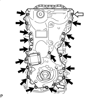

Bolt 
Nut Remove the 17 bolts and 2 nuts.
-
Remove the timing chain cover sub-assembly by prying between the timing chain cover sub-assembly and cylinder head sub-assembly, camshaft housing sub-assembly, cylinder block sub-assembly and stiffening crankcase assembly with a screwdriver as shown in the illustration.
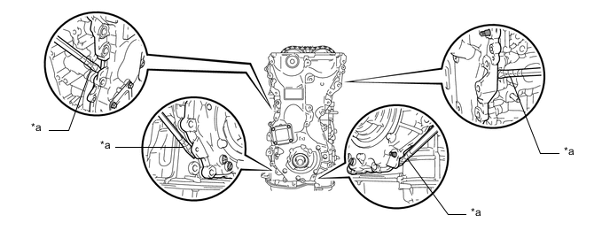
*a Protective Tape - - Note
Be careful not to damage the contact surfaces of the cylinder head sub-assembly, camshaft housing sub-assembly, cylinder block sub-assembly, stiffening crankcase assembly or timing chain cover sub-assembly.
Tech Tips
Tape the screwdriver tip before use.
-
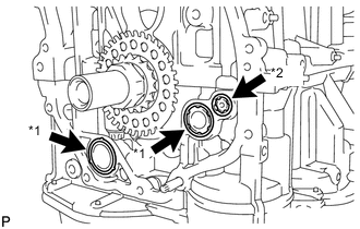
*1 Oil Pump Gasket *2 Oil Hole Cover Gasket Remove the 2 oil pump gaskets and oil hole cover gasket from the stiffening crankcase assembly.
-
-
REMOVE TIMING CHAIN COVER OIL SEAL