TELEMATICS SYSTEM(w/ Telematics Transceiver), Diagnostic DTC:B15DE
| DTC Code | DTC Name |
|---|---|
| B15DE | Telematics Transceiver Location Data Blackout |
DESCRIPTION
The telematics transceiver (Data Communication Module [DCM]) checks the reception condition of the location data every minute after the engine switch is turned on (ACC). If the location data is not received from the multi-media module receiver assembly for 5 minutes, this DTC will be stored.
DTC No. |
Detection Item |
DTC Detection Condition |
Trouble Area |
|---|---|---|---|
B15DE |
Telematics Transceiver Location Data Blackout |
Location information from USB communication is interrupted |
|
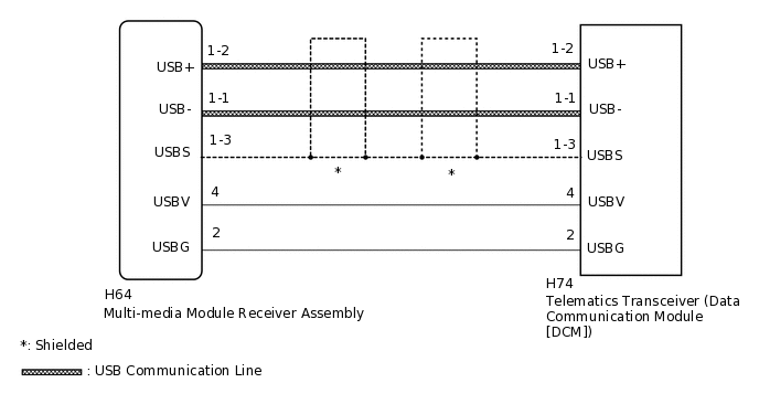
WIRING DIAGRAM
CAUTION / NOTICE / HINT
When replacing the multi-media module receiver assembly or the telematics transceiver (Data Communication Module [DCM]), perform the vehicle contract setting.
PROCEDURE
CHECK DTC OUTPUT
Clear the DTCs.
Body Electrical > Navigation System > Clear DTCs
Recheck for DTCs and check if the same DTC is output again.
Body Electrical > Navigation System > Trouble Codes
Result
Result
Proceed to
No DTCs are output.
A
B15DB and B15DE are output.
B
Only B15DE is output.
C
CHECK HARNESS AND CONNECTOR (TELEMATICS TRANSCEIVER [DATA COMMUNICATION MODULE (DCM)] - MULTI-MEDIA MODULE RECEIVER ASSEMBLY)
Check the installation condition.
Check the USB communication lines (digital communication cable) between the multi-media module receiver assembly and the telematics transceiver (Data Communication Module [DCM]) for any installation or connection problems.
Disconnect the H64 multi-media module receiver assembly connector.
Disconnect the H74 telematics transceiver (Data Communication Module [DCM]) connector.
Measure the resistance according to the value(s) in the table below.
Standard Resistance
Tester Connection
Condition
Specified Condition
H64-4 (USBV) - H74-4 (USBV)
Always
Below 1 Ω
H64-2 (USBG) - H74-2 (USBG)
Always
Below 1 Ω
H64-1-2 (USB+) - H74-1-2 (USB+)
Always
Below 1 Ω
H64-1-1 (USB-) - H74-1-1 (USB-)
Always
Below 1 Ω
H64-1-3 (USBS) - H74-1-3 (USBS)
Always
Below 1 Ω
H74-4 (USBV) - Body ground
Always
10 kΩ or higher
H74-2 (USBG) - Body ground
Always
10 kΩ or higher
H74-1-2 (USB+) - Body ground
Always
10 kΩ or higher
H74-1-1 (USB-) - Body ground
Always
10 kΩ or higher
H74-1-3 (USBS) - Body ground
Always
10 kΩ or higher
Result
Proceed to
OK
NG
NG REPAIR OR REPLACE HARNESS OR CONNECTOR
REPLACE TELEMATICS TRANSCEIVER (DATA COMMUNICATION MODULE [DCM])
Replace the telematics transceiver (Data Communication Module [DCM]).
Result
Proceed to
NEXT
CHECK DTC OUTPUT
Clear the DTCs.
Body Electrical > Navigation System > Clear DTCs
Recheck for DTCs and check if the same DTC is output again.
Body Electrical > Navigation System > Trouble Codes
Result
Result
Proceed to
B15DE is not output.
A
B15DE is output.
B
A END (TELEMATICS TRANSCEIVER [DATA COMMUNICATION MODULE (DCM)] IS DEFECTIVE)