TURBOCHARGER INSPECTION
PROCEDURE
-
INSPECT TURBINE WITH VALVE HOUSING SUB-ASSEMBLY
-
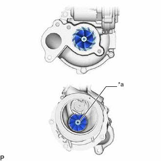
*a Center of Exhaust Side Turbine Check if the compressor side impeller and exhaust side turbine are damaged or defective.
Tech Tips
Wearing on the center of the exhaust side turbine is not a problem.
-
Move the rod by hand and check whether the waste gate valve is stuck.
-
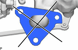
Using a straightedge and feeler gauge, measure the warpage of the turbine with valve housing sub-assembly installation surface.
Standard warpage 0.20 mm (0.00787 in.) If the result is not as specified, replace the turbocharger sub-assembly.
-
When the waste gate valve is fully closed, using a feeler gauge, measure the clearance between the waste gate valve and the contact surface of the turbine with valve housing sub-assembly waste gate valve port.
Standard clearance 0.50 mm (0.0197 in.) If the result is not as specified, replace the turbocharger sub-assembly.
-
-
INSPECT TURBINE SHAFT
-
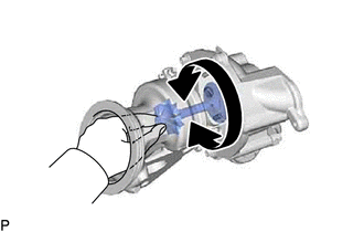
Grasp the compressor wheel nut with your fingers, and then turn the nut. Check that the compressor wheel rotates smoothly.
Note
If the compressor wheel does not rotate smoothly and there is interference between the turbine wheel and turbine with valve housing sub-assembly, replace the turbocharger sub-assembly at the same time.
Tech Tips
If the compressor wheel does not rotate smoothly, replace the turbocharger sub-assembly.
-
Check the turbine shaft in the axial direction.
-
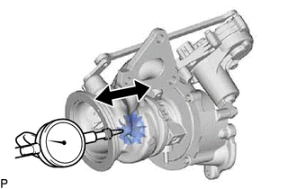
Set a dial indicator to the outlet side of the turbine shaft.
-
Move the turbine shaft in the axial direction and check for looseness.
Standard 0.10 mm (0.00394 in.) or less If the result is not as specified, replace the turbocharger sub-assembly.
-
-
INSPECT TURBOCHARGER WASTE GATE VALVE CONTROL ACTUATOR
-

*a Component without harness connected
(Turbocharger Sub-assembly)
for Bank 1:
Measure the resistance according to the value(s) in the table below.
Standard Resistance Tester Connection Condition Specified Condition D40-1(WG1-) - D40-2(WG1+) 20°C (68°F) 1 to 100 Ω If the result is not as specified, replace the turbocharger sub-assembly.
-
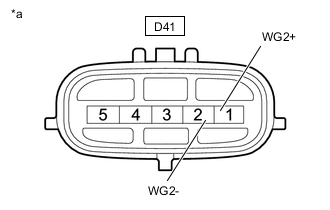
*a Component without harness connected
(Turbocharger Sub-assembly)
for Bank 2:
Measure the resistance according to the value(s) in the table below.
Standard Resistance Tester Connection Condition Specified Condition D41-1(WG2+) - D41-2(WG2-) 20°C (68°F) 1 to 100 Ω If the result is not as specified, replace the turbocharger sub-assembly.
-