AIR CONDITIONING SYSTEM
-
CONSTRUCTION
-
Front Air Conditioning Control Panel
-
Switches for the air conditioning system are located together in the center section of the instrument panel. To operate the air conditioning operation, both the switches located in the air conditioning control assembly and switches displayed on the multi display can be used.
-
In accordance with the adoption of the left and right independent temperature control system, the set temperature switches are provided separately for the driver side and front passenger side. In addition, the DUAL switch is provided to change the mode between cooperated operation mode and left and right independent temperature control mode.
-
For blower customization control, the multi-display has the FAST SOFT switch.
Figure 1. LHD Models
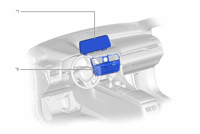
*1 Multi-display Assembly *2 Radio Receiver Assembly Figure 2. RHD Models
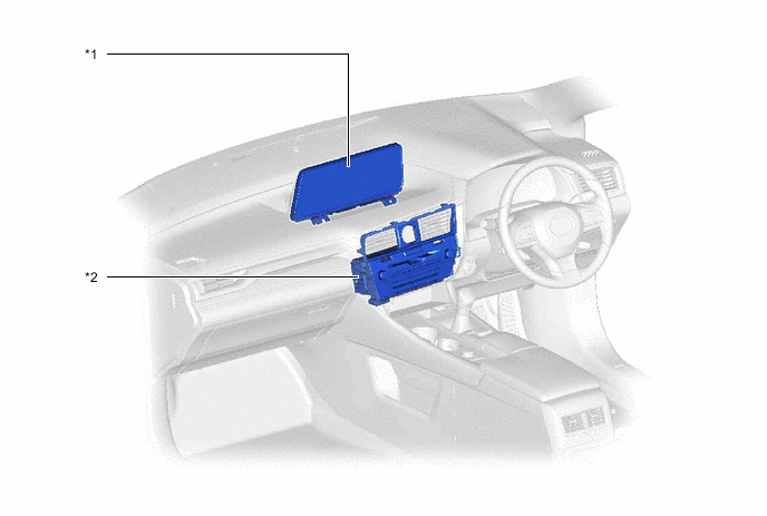
*1 Multi-display Assembly *2 Radio Receiver Assembly Figure 3. Multi-display Assembly
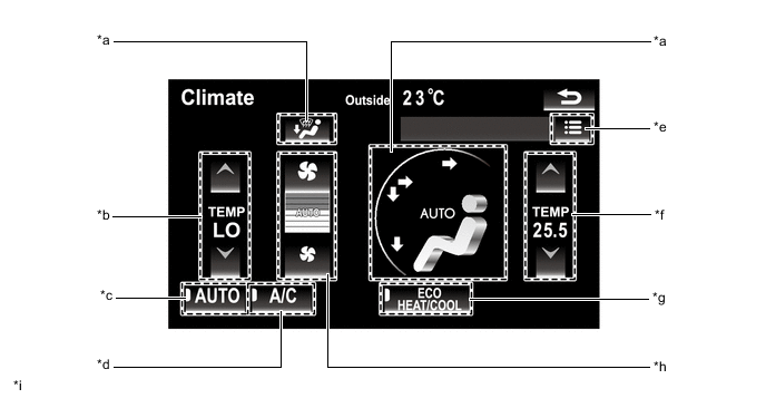
*a Air Outlet Mode Switch *b Temperature Control Switch (Driver Side) *c AUTO Switch *d A/C Switch *e Sub Menu Switch *f Temperature Control Switch (Front Passenger Side) *g ECO Air Conditioning Mode Switch *h Airflow Volume Switch *i The illustrations shown are examples only. - - Figure 4. Radio Receiver Assembly (LHD Models for Europe) (RX450h)
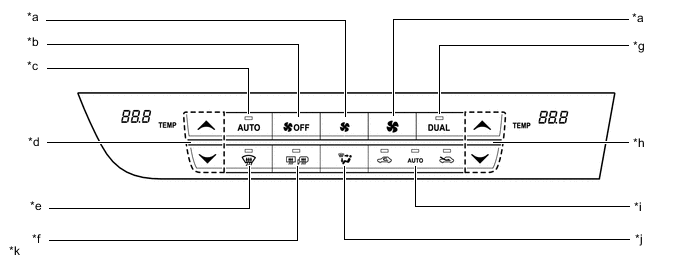
*a Airflow Volume Switch *b Blower Fan Off Switch *c AUTO Switch *d Temperature Control Switch (Driver Side) *e Front Defroster Switch *f Rear Window Defogger and Mirror Heater Switch *g DUAL Switch *h Temperature Control Switch (Front Passenger Side) *i Air Inlet Control Switch *j Air Outlet Mode Switch *k The illustrations shown are examples only. - - Figure 5. Radio Receiver Assembly (Models for G.C.C. Countries) (RX450h)
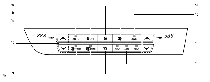
*a Airflow Volume Switch *b Blower Fan Off Switch *c AUTO Switch *d Temperature Control Switch (Driver Side) *e Front Defroster Switch *f Rear Window Defogger Switch *g DUAL Switch *h Temperature Control Switch (Front Passenger Side) *i Air Inlet Control Switch *j Air Outlet Mode Switch *k The illustrations shown are examples only. - - Figure 6. Radio Receiver Assembly (LHD Models for General Countries) (RX450h)

*a Airflow Volume Switch *b Blower Fan Off Switch *c AUTO Switch *d Temperature Control Switch (Driver Side) *e Front Defroster Switch *f Rear Window Defogger and Mirror Heater Switch *g DUAL Switch *h Temperature Control Switch (Front Passenger Side) *i Air Inlet Control Switch *j Air Outlet Mode Switch *k The illustrations shown are examples only. - - Figure 7. Radio Receiver Assembly (Models for China or Destination Package for South Korea) (RX450h)
*a Airflow Volume Switch *b Blower Fan Off Switch *c AUTO Switch *d Temperature Control Switch (Driver Side) *e Front Defroster Switch *f Rear Window Defogger and Mirror Heater Switch *g DUAL Switch *h Temperature Control Switch (Front Passenger Side) *i Air Inlet Control Switch *j Air Outlet Mode Switch *k The illustrations shown are examples only. - - Figure 8. Radio Receiver Assembly (RHD Models for Europe) (RX450h)
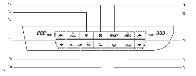
*a Airflow Volume Switch *b DUAL Switch *c Temperature Control Switch (Front Passenger Side) *d Air Inlet Control Switch *e Air Outlet Mode Switch *f Blower Fan Off Switch *g AUTO Switch *h Temperature Control Switch (Driver Side) *i Rear Window Defogger and Mirror Heater Switch *j Front Defroster Switch *k The illustrations shown are examples only. - - Figure 9. Radio Receiver Assembly (RHD Models for General Countries or Destination Package for Australia) (RX450h)
*a Airflow Volume Switch *b DUAL Switch *c Temperature Control Switch (Front Passenger Side) *d Air Inlet Control Switch *e Air Outlet Mode Switch *f Blower Fan Off Switch *g AUTO Switch *h Temperature Control Switch (Driver Side) *i Rear Window Defogger and Mirror Heater Switch *j Front Defroster Switch *k The illustrations shown are examples only. - - Figure 10. Radio Receiver Assembly (Models for G.C.C. Countries) (RX450hL)
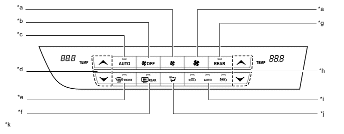
*a Airflow Volume Switch *b Blower Fan Off Switch *c AUTO Switch *d Temperature Control Switch (Driver Side) *e Front Defroster Switch *f Rear Window Defogger Switch *g REAR Switch *h Temperature Control Switch (Front Passenger Side) *i Air Inlet Control Switch *j Air Outlet Mode Switch *k The illustrations shown are examples only. - - Figure 11. Radio Receiver Assembly (LHD Models for General Countries) (RX450hL)
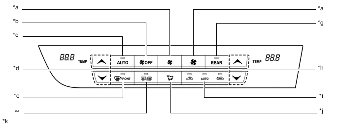
*a Airflow Volume Switch *b Blower Fan Off Switch *c AUTO Switch *d Temperature Control Switch (Driver Side) *e Front Defroster Switch *f Rear Window Defogger and Mirror Heater Switch *g REAR Switch *h Temperature Control Switch (Front Passenger Side) *i Air Inlet Control Switch *j Air Outlet Mode Switch *k The illustrations shown are examples only. - - Figure 12. Radio Receiver Assembly (RHD Models for General Countries or Destination Package for Australia) (RX450hL)
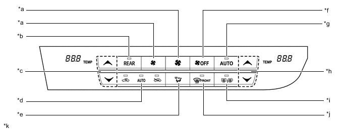
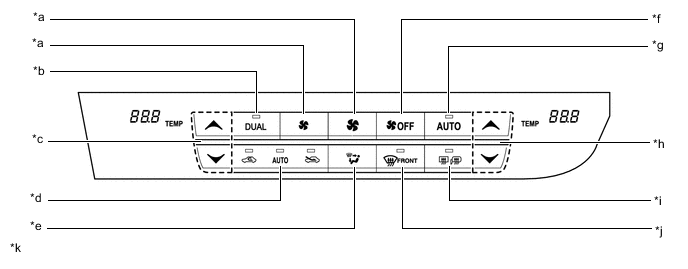
*a Airflow Volume Switch *b REAR Switch *c Temperature Control Switch (Front Passenger Side) *d Air Inlet Control Switch *e Air Outlet Mode Switch *f Blower Fan Off Switch *g AUTO Switch *h Temperature Control Switch (Driver Side) *i Rear Window Defogger and Mirror Heater Switch *j Front Defroster Switch *k The illustrations shown are examples only. - -
-
-
Rear Air Conditioning Control Panel
-
The rear air conditioning system can be operated by the No. 2 air conditioning control assembly or the multi-display assembly.
-
The No. 2 air conditioning control assembly is located in the quarter trim board, which displays the set temperature, air outlet mode and airflow volume on its display.
Figure 13. Multi-display Assembly
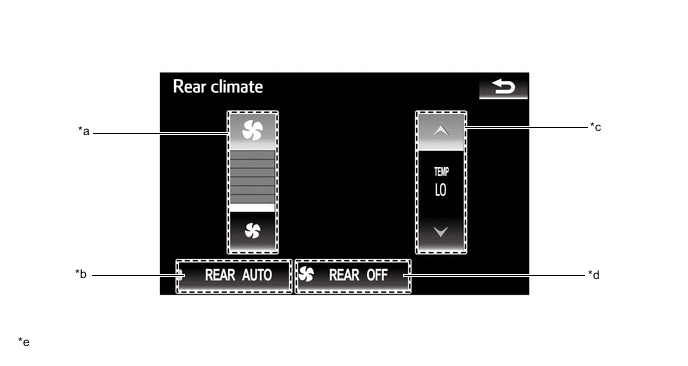
*a Airflow Volume Switch *b AUTO Switch *c Temperature Control Switch *d Blower Fan Off Switch *e The illustrations shown are examples only. - - Figure 14. No. 2 Air Conditioning Control Assembly
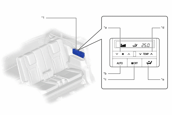
*1 No. 2 Air Conditioning Control Assembly - - *a Airflow Volume Switch *b AUTO Switch *c Blower Fan Off Switch *d Temperature Control Switch *e Air Outlet Mode Switch - -
-
-