CONTINUOUSLY VARIABLE TRANSAXLE SYSTEM, Diagnostic DTC:P1585
| DTC Code | DTC Name |
|---|---|
| P1585 | Acceleration Sensor Circuit |
DESCRIPTION
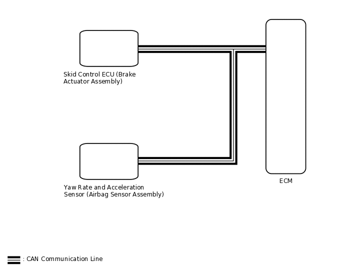
The ECM determines the vehicle inclination based on a signal from the yaw rate and acceleration sensor (airbag sensor assembly). If a malfunction in the yaw rate and acceleration sensor (airbag sensor assembly) is determined based on a malfunction signal from the skid control ECU (brake actuator assembly), the ECM stores this DTC.
The yaw rate and acceleration sensor (airbag sensor assembly) signal is sent to the skid control ECU (brake actuator assembly) via CAN communication.
If CAN communication DTCs are output, perform troubleshooting for those DTCs first.
DTC No. |
Detection Item |
DTC Detection Condition |
Trouble Area |
MIL |
Memory |
|---|---|---|---|---|---|
P1585 |
Acceleration Sensor Circuit |
1. Diagnosis Condition 2. Malfunction Status 3. Malfunction Time 4. Other DTC Detection Condition 1:
DTC Detection Condition 2:
DTC Detection Condition 3:
DTC Detection Condition 4:
DTC Detection Condition 5:
|
|
Does not come on |
DTC stored |
WIRING DIAGRAM
CAUTION / NOTICE / HINT
Perform initialization when parts related to the continuously variable transaxle are replaced.
Check that no DTCs are stored after performing initialization.
PROCEDURE
CHECK DTC OUTPUT
Connect the GTS to the DLC3.
Turn the ignition switch to ON.
Turn the GTS on.
Check for DTCs.
Powertrain > Engine and ECT > Trouble Codes
Result
Result
Proceed to
DTC U0129 is not output
A
DTC U0129 is output
B
B GO TO CAN COMMUNICATION SYSTEM
for LHD with Central Gateway ECU:
for RHD with Central Gateway ECU:
for LHD without Central Gateway ECU:
for RHD without Central Gateway ECU:
READ VALUE USING GTS (G SENSOR)
Connect the GTS to the DLC3.
Turn the ignition switch to ON.
Turn the GTS on.
Enter the following menus: Powertrain / Engine and ECT / Data List / Primary.
In accordance with the display on the GTS, read the Data List.
Powertrain > Engine and ECT > Data List
Tester Display
Measurement Item
Range
Normal Condition
Diagnostic Note
G Sensor
Converted output voltage of G sensor
Min.: 0 V
Max.: 79.998 V
Displays converted voltage of G sensor
2.31 V to 2.69 V: Vehicle on level ground
1.88 V to 2.5 V: Decelerating
2.5 V to 3.11 V: Accelerating
Set to 1.87 V: G sensor malfunction
Set to 1.87 V: Communication malfunction
-
Powertrain > Engine and ECT > Data List
Tester Display
G Sensor
Result
Result
Proceed to
Data display is not within Normal Condition range
A
Data display is within Normal Condition range
B
REPLACE AIRBAG SENSOR ASSEMBLY
Replace the yaw rate and acceleration sensor (airbag sensor assembly).
Result
Proceed to
NEXT