LIGHTING SYSTEM, Diagnostic DTC:B2416 and B241A
| DTC Code | DTC Name |
|---|---|
| B2416 | Height Control Sensor Malfunction |
| B241A | Rear Height Control Sensor |
DESCRIPTION
The headlight leveling ECU receives signals indicating the height of the vehicle from the height control sensor.
DTC Code |
DTC Detection Condition |
Trouble Area |
|---|---|---|
B2416 |
Either condition is met:
|
|
B241A |
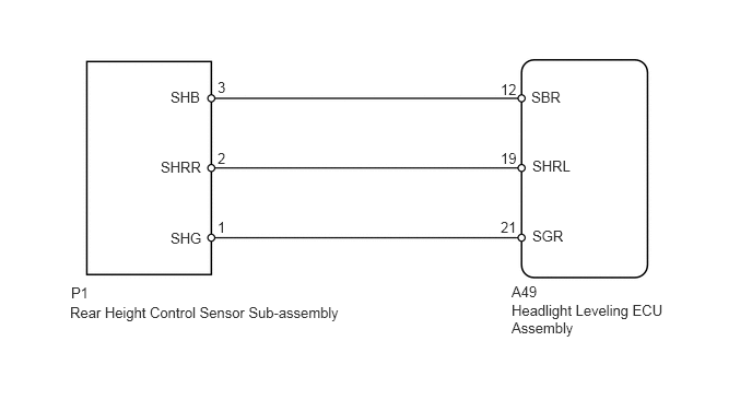
WIRING DIAGRAM
CAUTION / NOTICE / HINT
After replacing the headlight leveling ECU, initialization of the ECU is necessary (Click here).
PROCEDURE
READ VALUE USING INTELLIGENT TESTER
Using the intelligent tester, read the Data List (Click here).
Table 1. HL Auto Leveling Tester Display
Measurement Item/Range
Normal Condition
Diagnostic Note
Height Sens Pw Supply Val
Rear height control sensor power supply value / 0 to 5 V
Approximately 5.0 V
-
Rr Height Sens Signal Val
Rear height control sensor signal value / 0 to 5 V
Approximately 2.5 V (When vehicle level)
The value becomes larger when the front of the vehicle tilts up.
OK
The display is as specified in the normal condition column.
Table 2. Result Result
Proceed to
NG
A
OK (for LHD)
B
OK (for RHD)
C
CHECK HARNESS AND CONNECTOR (HEADLIGHT LEVELING ECU ASSEMBLY - REAR HEIGHT CONTROL SENSOR SUB-ASSEMBLY)
-
Disconnect the A49 headlight leveling ECU connector.
Disconnect the P1 height control sensor connector.
Measure the resistance according to the value(s) in the table below.
Standard Resistance
Tester Connection
Condition
Specified Condition
A49-12 (SBR) - P1-3 (SHB)
Always
Below 1 Ω
A49-19 (SHRL) - P1-2 (SHRR)
Always
Below 1 Ω
A49-21 (SGR) - P1-1 (SHG)
Always
Below 1 Ω
A49-12 (SBR) - Body ground
Always
10 kΩ or higher
A49-19 (SHRL) - Body ground
Always
10 kΩ or higher
A49-21 (SGR) - Body ground
Always
10 kΩ or higher
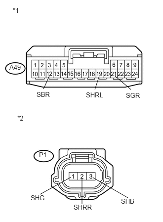
Table 3. Text in Illustration *1
Front view of wire harness connector
(to Headlight Leveling ECU Assembly)
*2
Front view of wire harness connector
(to Rear Height Control Sensor Sub-assembly)
REPAIR OR REPLACE HARNESS OR CONNECTOR
-
CHECK HEADLIGHT LEVELING ECU ASSEMBLY
-
Reconnect the A49 headlight leveling ECU connector.
Measure the voltage according to the value(s) in the table below.
Standard Voltage
Tester Connection
Switch Condition
Specified Condition
A49-12 (SBR) - A49-21 (SGR)
Ignition switch ON
4.75 to 5.25 V
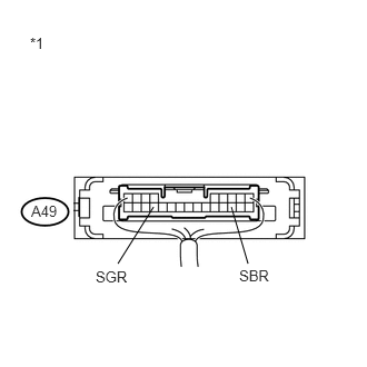
Table 4. Text in Illustration *1
Component with harness connected
(Headlight Leveling ECU Assembly)
Table 5. Result Result
Proceed to
OK
A
NG (for LHD)
B
NG (for RHD)
C
-
INSPECT REAR HEIGHT CONTROL SENSOR SUB-ASSEMBLY
Remove the height control sensor (Click here).
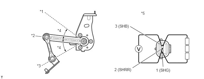
Table 6. Text in Illustration *1
Min. Low
*2
Normal
*3
Max. High
*4
45°
*5
Component without harness connected
(Rear Height Control Sensor Sub-assembly)
-
-
Connect 3 dry cell batteries (1.5 V) in series.
Connect the positive (+) lead from the batteries to terminal 3, and the negative (-) lead from the batteries to terminal 1.
Measure the voltage according to the value(s) in the table below.
Standard Voltage
Tester Connection
Condition
Specified Condition
2 (SHRR) - 1 (SHG)
Max. high
Approximately 4.5 V
Normal
Approximately 2.5 V
Min. low
Approximately 0.5 V
Table 7. Result Result
Proceed to
OK (for LHD)
A
OK (for RHD)
B
NG
C