CONTINUOUSLY VARIABLE TRANSAXLE SYSTEM Pattern Select Switch Sport Mode Circuit
| DTC Code | DTC Name |
|---|---|
| Pattern Select Switch Sport Mode Circuit |
DESCRIPTION
The ECM memory contains the programs for the normal and sport shift patterns.
By following the programs corresponding to the signals from the pattern select switch assembly, the park/neutral position switch and other various sensors, the ECM switches the shift control solenoid valves on and off, and controls the transaxle gear ratio.
WIRING DIAGRAM
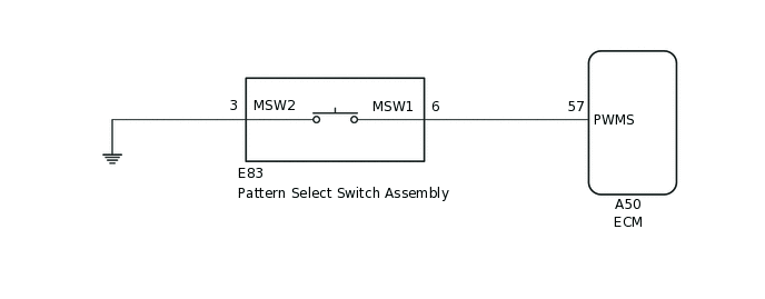
PROCEDURE
READ VALUE USING GTS (PATTERN SWITCH (PWR/M))
Connect the GTS to the DLC3.
Turn the ignition switch to ON.
Turn the GTS on.
Enter the following menus: Powertrain / Engine and ECT / Data List / Primary.
In accordance with the display on the GTS, read the Data List.
Powertrain > Engine and ECT > Data List
Tester Display
Measurement Item
Range
Normal Condition
Diagnostic Note
Pattern Switch (PWR/M)
Pattern select switch (SPORT) status
OFF or ON
OFF: Sport mode off
ON: Sport mode on
-
Result
Result
Proceed to
Data display is within Normal Condition range
A
Data display is not within Normal Condition range
B
B INSPECT PATTERN SELECT SWITCH ASSEMBLYClick here
REPLACE ECM
Replace the ECM.
for 1ZR-FE:Click here
for 2ZR-FE:Click here
Result
Proceed to
NEXT
INSPECT PATTERN SELECT SWITCH ASSEMBLY
-
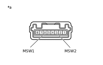
*a
Component without harness connected
(Pattern select switch assembly)
Remove the pattern select switch assembly.
Measure the resistance according to the value(s) in the table below.
Standard Resistance
Tester Connection
Condition
Specified Condition
6 (MSW1) - 3 (MSW2)
Pattern select switch on
Below 1 Ω
6 (MSW1) - 3 (MSW2)
Pattern select switch off
10 kΩ or higher
Result
Proceed to
OK
NG
-
CHECK HARNESS AND CONNECTOR (PATTERN SELECT SWITCH ASSEMBLY - BODY GROUND)
Measure the resistance according to the value(s) in the table below.
Standard Resistance
Tester Connection
Condition
Specified Condition
E83-3 (MSW2) - Body ground
Always
Below 1 Ω
Install the pattern select switch assembly.
Result
Proceed to
OK
NG
NG REPAIR OR REPLACE HARNESS OR CONNECTOR (PATTERN SELECT SWITCH ASSEMBLY - BODY GROUND)
CHECK HARNESS AND CONNECTOR (PATTERN SELECT SWITCH ASSEMBLY - ECM)
Disconnect the A50 ECM connector.
Measure the resistance according to the value(s) in the table below.
Standard Resistance
Tester Connection
Condition
Specified Condition
A50-57 (PWMS) - Body ground
Pattern select switch on
Below 1 Ω
A50-57 (PWMS) - Body ground
Pattern select switch off
10 kΩ or higher
Connect the A50 ECM connector.
Result
Proceed to
OK
NG
NG REPAIR OR REPLACE HARNESS OR CONNECTOR (PATTERN SELECT SWITCH ASSEMBLY - ECM)
REPLACE ECM
Replace the ECM.
for 1ZR-FE:Click here
for 2ZR-FE:Click here
Result
Proceed to
NEXT