FRONT AXLE HUB INSTALLATION

-
INSTALL FRONT AXLE HUB BEARING
-
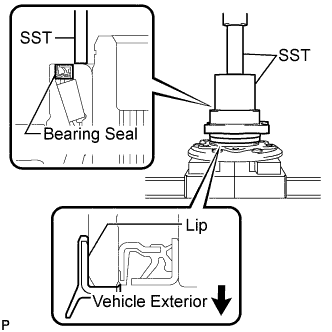
Using SST and a press, install a new front axle hub bearing.
- SST
- 09649-17010
- 09950-70010 ( 09951-07100 )
Note
Do not press on or damage the bearing seal of the front axle hub bearing.
Tech Tips
Make sure the lip of the front axle hub bearing faces the vehicle exterior.
-
-
INSTALL FRONT DISC
-
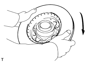
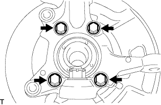
Install the front disc as shown in the illustration.
-
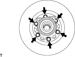
Install the front disc with the 6 bolts.
- Torque:
- 62 N*m { 632 kgf*cm, 46 ft.*lbf }
-
-
INSTALL FRONT WHEEL ADJUSTING NUT (w/ ABS)
-
Install the hub nut to the front axle hub bolt.
-
Hold the front axle assembly in a vise between aluminium plates.
Note
-
Do not overtighten the vise.
-
Hold the hub nut in a vise to secure the axle hub and bearing assembly.
-
-
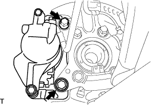
Install the skid control rotor as shown in the illustration.
-
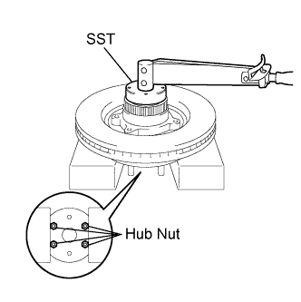
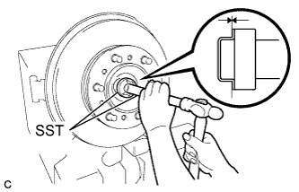
Using SST, install the front wheel adjusting nut.
- SST
- 09607-26010
- Torque:
- 287 N*m { 2,930 kgf*cm, 212 ft.*lbf }
Note
Do not use an extension bar to avoid applying excess torque to the nut and rotor.
-
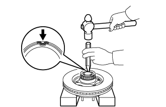
Using a chisel and hammer, stake the front wheel adjusting nut.
-
-
INSTALL FRONT WHEEL ADJUSTING NUT (w/o ABS)
-
Install the hub nut to the front axle hub bolt.
-
Hold the front axle assembly in a vise between aluminium plates.
Note
-
Do not overtighten the vise.
-
Hold the hub nut in a vise to secure the axle hub and bearing assembly.
-
-
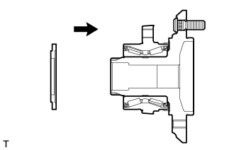
Install the front wheel bearing dust deflector as shown in the illustration.
-
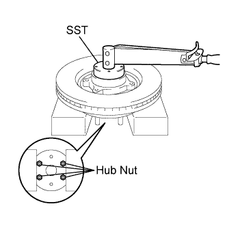
Using SST, install the front wheel adjusting nut.
- SST
- 09607-26010
- Torque:
- 287 N*m { 2,930 kgf*cm, 212 ft.*lbf }
Note
Do not use an extension bar to avoid applying excess torque to the nut and rotor.
-
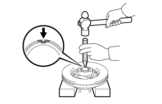
Using a chisel and hammer, stake the front wheel adjusting nut.
-
-
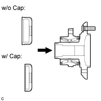
INSTALL INNER KNUCKLE GREASE RETAINER CAP (w/ Cap)
-
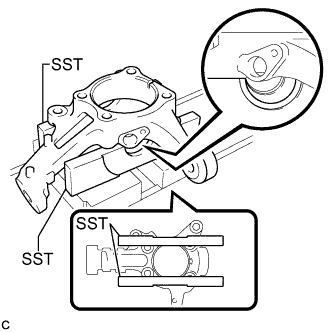
Using SST, place the steering knuckle on a press as shown in the illustration.
- SST
- 09527-30010
-
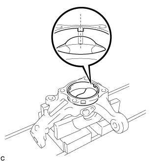
Temporarily install a new inner knuckle grease retainer cap to the steering knuckle as shown in the illustration.
Note
Align the center of the cutout in the inner knuckle grease retainer cap and the groove of the steering knuckle.
-
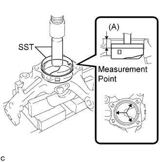
Using SST and the press, press the inner knuckle grease retainer cap into the steering knuckle until the distance (A) in the illustration meets the standard value.
- SST
- 09950-70010 ( 09951-07100 )
- 09951-00900
Distance (A) 26 +/- 0.5 mm (1.02 +/- 0.0196 in.) Note
Using a vernier caliper, measure the distance (A) at the 3 points indicated by the arrows in the illustration while pressing.
-
-
INSTALL FRONT LOWER BALL JOINT ASSEMBLY
-
Fix the steering knuckle in the vise using aluminium plates.
Note
Do not damage the steering knuckle.
-
Install the front lower ball joint assembly to the steering knuckle with the nut.
- Torque:
- 170 N*m { 1,730 kgf*cm, 125 ft.*lbf }
Note
-
Ensure that the thread and taper are free of oil etc.
-
Do not damage the lower ball joint dust boot.
-
Install a new cotter pin to the front lower ball joint assembly.
Note
Further tighten the nut up to 60° if the holes for the cotter pin are not aligned.
-
-
INSTALL STEERING KNUCKLE
-
Install the steering knuckle and brake dust cover to the front axle hub sub-assembly with the 4 bolts.
- Torque:
- 88 N*m { 897 kgf*cm, 65 ft.*lbf }
-
-
INSTALL OUTER KNUCKLE GREASE RETAINER CAP (w/ Cap)
-
Using SST, install a new outer knuckle grease retainer cap.
- SST
- 09950-60010 ( 09951-00420 )
- 09950-70010 ( 09951-07150 )
-
-
INSTALL FRONT AXLE ASSEMBLY
-
Temporarily install the front axle assembly to the front suspension upper arm and front suspension lower arm.
-
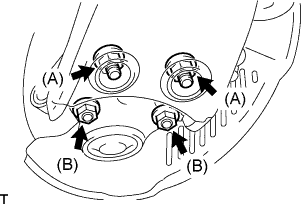
Fully tighten front suspension lower arm with the 4 bolts and 4 nuts.
- Torque:
- Nut (A)
- 90 N*m { 918 kgf*cm, 66 ft.*lbf }
- Nut (B)
- 52 N*m { 530 kgf*cm, 38 ft.*lbf }
-
Fully tighten the front suspension upper arm with the nut.
- Torque:
- 113 N*m { 1,147 kgf*cm, 83 ft.*lbf }
Note
Do not damage the lower ball joint dust boot.
-
Install a new cotter pin to the front suspension upper arm.
Note
Further tighten the castle nut up to 60° if the holes for the cotter pin are not aligned.
-
-
INSTALL TIE ROD END SUB-ASSEMBLY
-
Install the tie rod end sub-assembly to the steering knuckle with the castle nut.
- Torque:
- 50 N*m { 510 kgf*cm, 37 ft.*lbf }
Note
Do not damage the lower ball joint dust boot.
-
Install a new cotter pin to the tie rod end sub-assembly.
Note
Further tighten the castle nut up to 60° if the holes for the cotter pin are not aligned.
-
-
INSTALL FRONT DISC BRAKE CALIPER ASSEMBLY
-
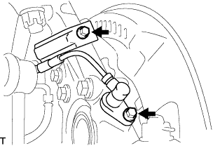
Install the brake caliper assembly to the steering knuckle with the 2 bolts.
- Torque:
- 123 N*m { 1,250 kgf*cm, 91 ft.*lbf }
-
-
INSTALL FRONT SPEED SENSOR (w/ ABS)
-
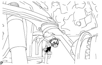
Install the speed sensor to the steering knuckle with the 2 bolts.
- Torque:
- 8.5 N*m { 87 kgf*cm, 75 in.*lbf }
Note
-
Prevent foreign matter from adhering to the speed sensor.
-
Be careful not to damage the speed sensor.
-
Do not twist the sensor wire when installing the speed sensor.
-
-
INSPECT FRONT AXLE HUB BEARING LOOSENESS
-
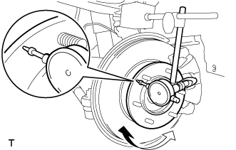
Using a dial indicator, check for runout on the surface of the front axle hub outside the hub bolt.
Maximum 0.07 mm (0.0028 in.) Note
Ensure that the dial indicator is set at right angles to the measurement surface.
If runout exceeds the maximum, replace the front axle hub.
-
-
INSPECT FRONT AXLE HUB RUNOUT
-
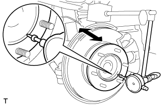
Using a dial indicator, check for looseness near the center of the front axle hub.
Maximum 0.05 mm (0.0020 in.) Note
Ensure that the dial indicator is set at right angles to the measurement surface.
If looseness exceeds the maximum, replace the bearing.
-
-
INSTALL FRONT WHEEL
- Torque:
- 100 N*m { 1,020 kgf*cm, 74 ft.*lbf }
-
INSPECT WHEEL ALIGNMENT
-
CHECK ABS SPEED SENSOR SIGNAL