CAN COMMUNICATION SYSTEM SYSTEM DIAGRAM
OVERALL CAN BUS DIAGRAM
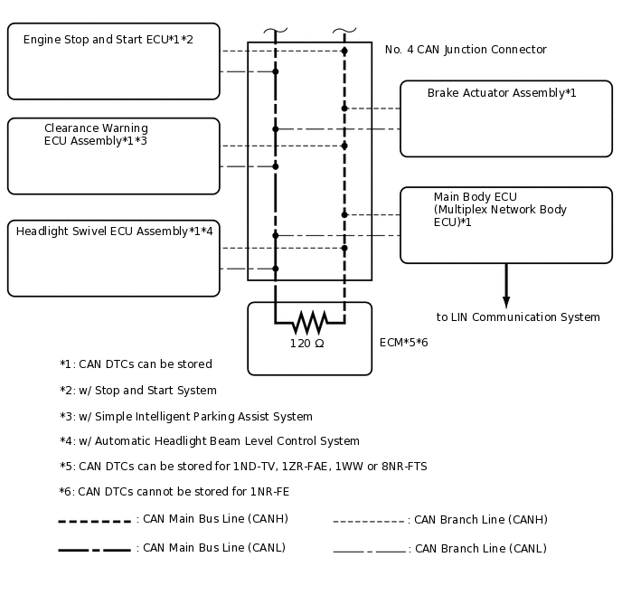
The CAN communication system is composed of 1 bus.
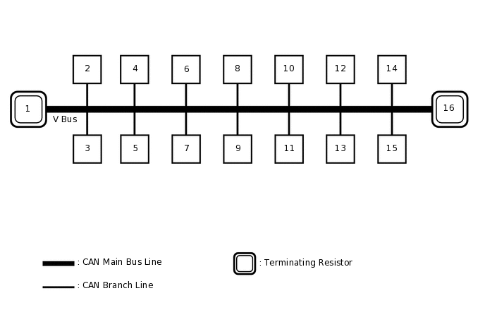
1
Combination Meter Assembly
2
Certification ECU (Smart Key ECU Assembly)
(w/ Entry and Start System)
3
Steering Sensor (Spiral Cable with Sensor Sub-assembly)
(w/ VSC)
4
Radio and Display Receiver Assembly
(for Radio and Display Type)
5
Airbag Sensor Assembly
6
Power Steering ECU Assembly
7
Air Conditioning Amplifier Assembly
(w/ Air Conditioning System)
8
Clearance Warning ECU Assembly
(w/ Simple Intelligent Parking Assist System)
9
Engine Stop and Start ECU
(w/ Stop and Start System)
10
Brake Actuator Assembly
11
DLC3
12
Main Body ECU (Multiplex Network Body ECU)
13
Headlight Swivel ECU Assembly
(w/ Automatic Headlight Beam Level Control System)
14
Driving Support ECU Assembly
(for 1ND-TV with Driving Support ECU)
15
Pre-crash Safety City Sensor
(w/ Toyota Safety Sense)
16
ECM
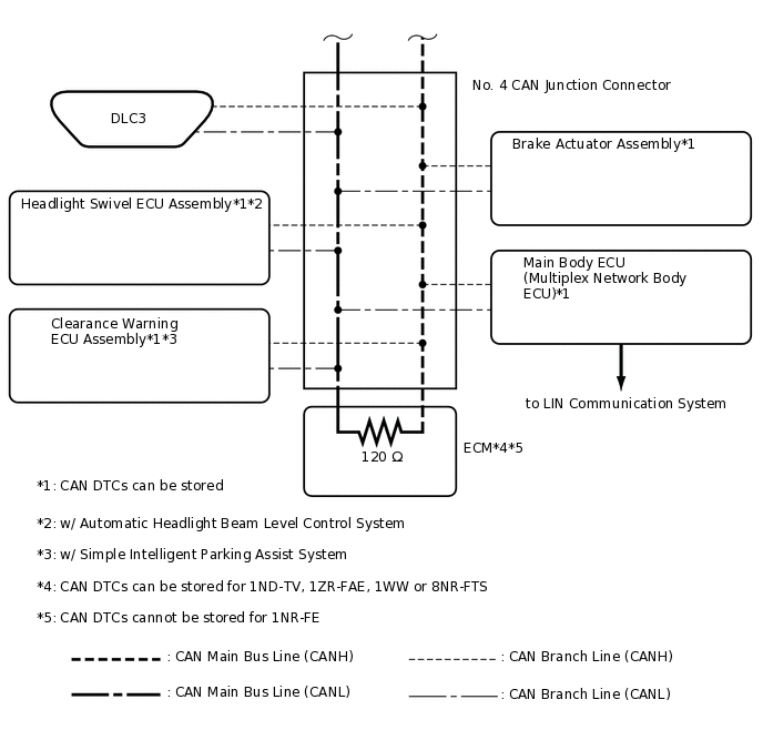
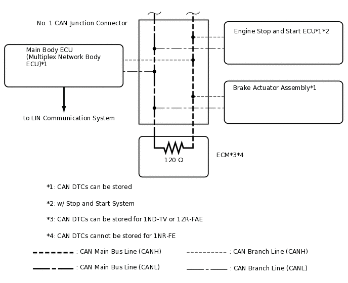
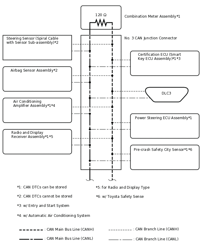
Tip:Refer to the following bus wiring diagrams for details.
V BUS (for LHD Sedan)
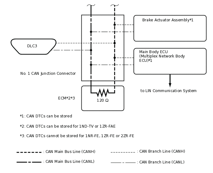 Tip:
Tip:The CAN communication system connects to other networks via ECUs that function as a gateway.
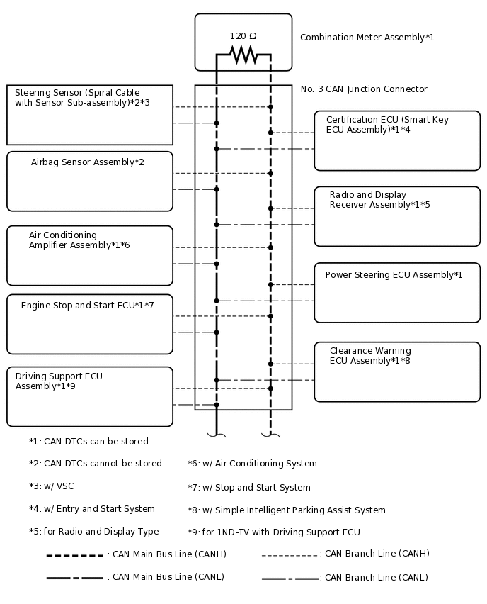
V BUS (for LHD except Sedan)
 Tip:
Tip:The CAN communication system connects to other networks via ECUs that function as a gateway.
V BUS (for RHD Sedan)
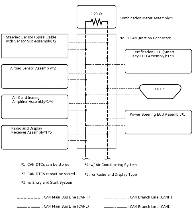
 Tip:
Tip:The CAN communication system connects to other networks via ECUs that function as a gateway.
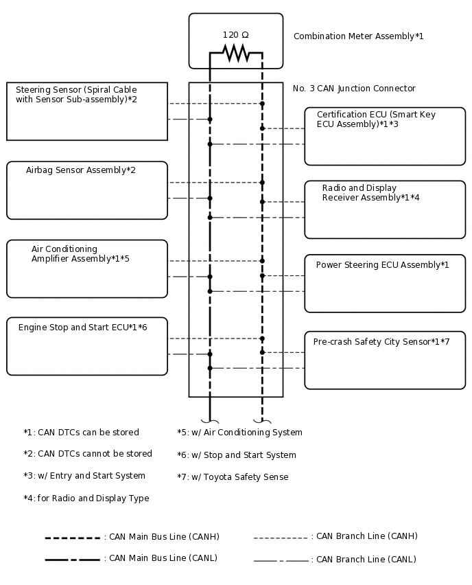
V BUS (for RHD except Sedan)
 Tip:
Tip:The CAN communication system connects to other networks via ECUs that function as a gateway.