CAN COMMUNICATION SYSTEM(for LHD) SYSTEM DIAGRAM
SYSTEM DIAGRAM
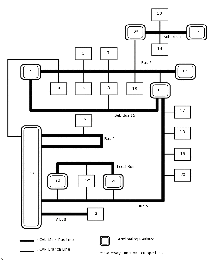
Overall CAN Bus Diagram
Control system CAN is composed of 7 buses.
No.
ECU/Sensor Name
1
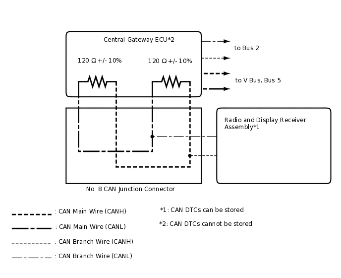
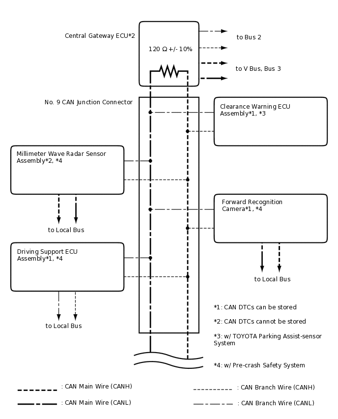
Central gateway ECU
2
DLC3
3
ECM
4
Power steering ECU assembly
5
Air conditioning amplifier assembly
6
Airbag sensor assembly
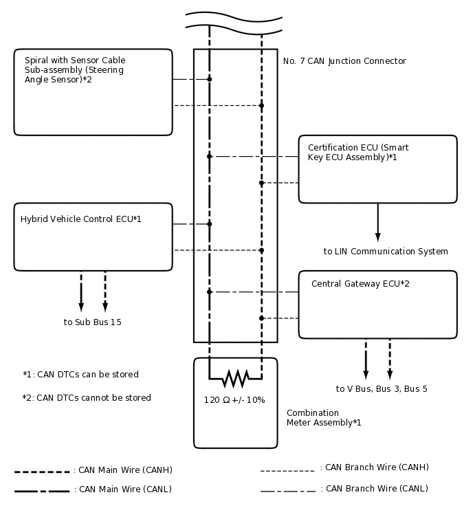
7
Spiral with sensor cable sub-assembly (steering angle sensor)
8
Brake booster with master cylinder assembly (skid control ECU)
9
Main body ECU (multiplex network body ECU)
10
Certification ECU (smart key ECU assembly)
11
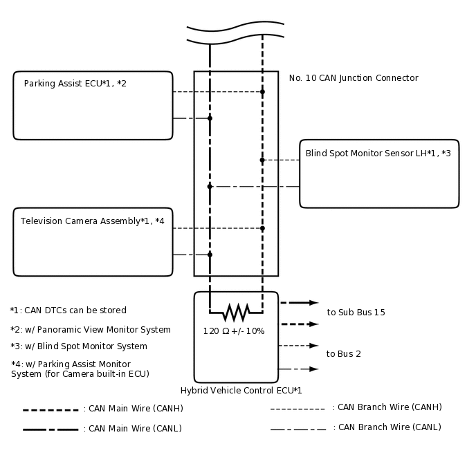
Hybrid vehicle control ECU
12
Combination meter assembly
13
Multiplex network door ECU*1
14
Position control ECU and switch assembly*2
15
No. 1 CAN junction terminal*1
16
Radio and display receiver assembly*3
17
Parking assist ECU*4
18
Clearance warning ECU assembly*5
19
Blind spot monitor sensor LH*6
20
Television camera assembly*7
21
Millimeter wave radar sensor assembly*8
22
Driving support ECU assembly*8
23
Forward recognition camera*8
*1: w/ Power Back Door System
*2: w/ Seat Memory
*3: w/ Audio and Visual System (for Radio and Display Type)
*4: w/ Panoramic View Monitor System
*5: w/ TOYOTA Parking Assist-sensor System
*6: w/ Blind Spot Monitor System
*7: w/ Parking Assist Monitor System (for Camera built-in ECU)
*8: w/ Pre-crash Safety System
Tip:The main body ECU (multiplex network body ECU) functions as a gateway between the bus 2 and sub bus 1.
The driving support ECU assembly functions as a gateway between the bus 5 and local bus.
Refer to the following bus wiring diagrams for details.
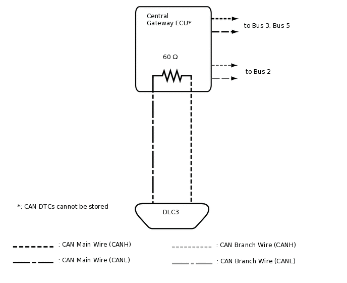
V Bus
Bus 2
Bus 3 (w/ Audio and Visual System [for Radio and Display Type])
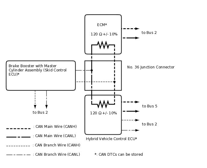
Bus 5
Sub Bus 1 (w/ Power Back Door System)
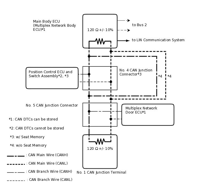 Tip:
Tip:The CAN communication system connects to other networks via ECUs that function as a gateway.
Local Bus (w/ Pre-crash Safety System)
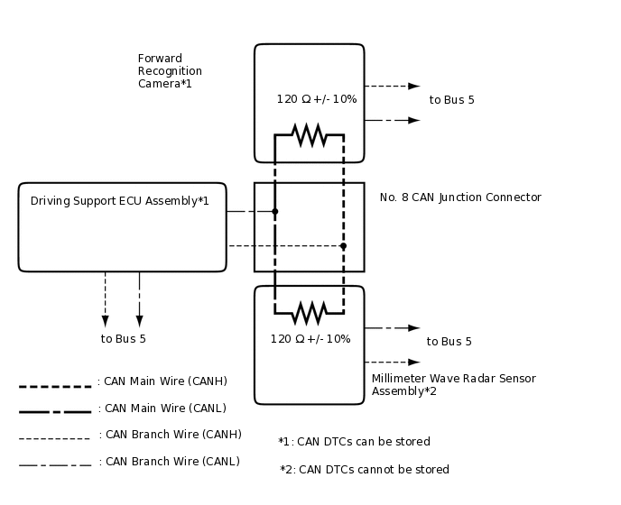
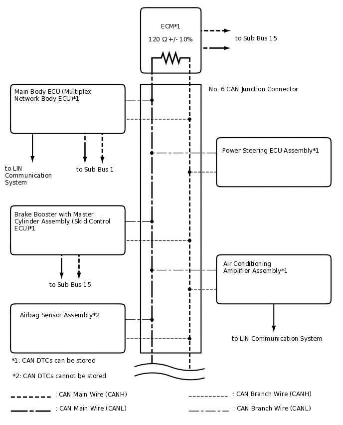
Sub Bus 15