NAVIGATION SYSTEM Radio Broadcast cannot be Received or Poor Reception
| DTC Code | DTC Name |
|---|---|
| Radio Broadcast cannot be Received or Poor Reception |
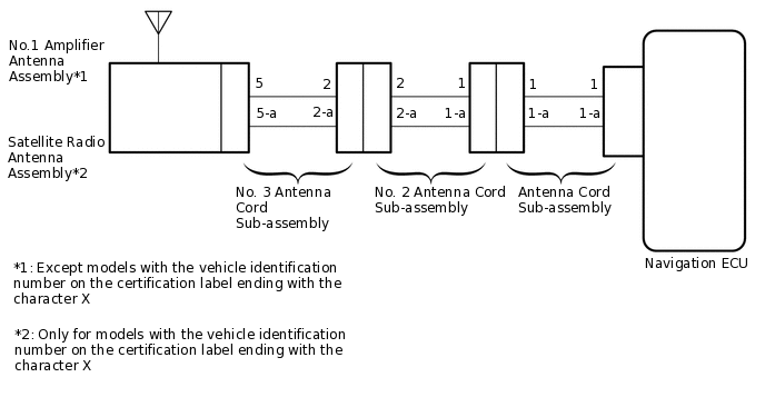
WIRING DIAGRAM
CAUTION / NOTICE / HINT
Check that the wire harness is properly installed and does not have any sharp bends, pinching or loose connections.
PROCEDURE
CHECK IF RADIO AUTO-SEARCH FUNCTIONS PROPERLY
Check the radio automatic station search function by activating it.
OK
Automatic station search function stops on a station.
Result
Proceed to
OK
NG
CHECK OPTIONAL COMPONENTS
Check if any optional components that may decrease reception capacity, such as sunshade film or a telephone antenna, are installed.
OK
Optional components are installed.
Note:Do not remove optional components without permission of the customer.
Result
Proceed to
OK
NG
OK REMOVE OPTIONAL COMPONENTS AND CHECK AGAIN (SEE NOTICE ABOVE)
CHECK RADIO AND DISPLAY RECEIVER ASSEMBLY (ANTENNA)
-
Remove the antenna connector from the radio and display receiver assembly.
Turn the power switch on (ACC) with the radio and display receiver assembly connector connected.
Turn on the radio and turn into AM mode.
Place a screwdriver, thin wire or other metal object on the radio and display receiver assembly antenna jack and check that noise can be heard from the speakers.
OK
Noise occurs.
Result
Proceed to
OK
NG
-
INSPECT RADIO AND DISPLAY RECEIVER ASSEMBLY
Disconnect the RA radio and display receiver assembly connector.
-
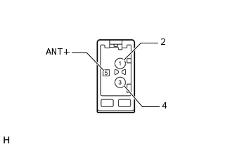
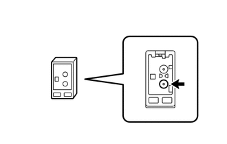
Measure the voltage according to the value(s) in the table below.
Standard Voltage
Tester Connection
Switch Condition
Specified Condition
5 (ANT+) - Body ground
Power switch on (ACC), radio switch on and FM or AM selected
11 to 14 V
Result
Proceed to
OK
NG
CHECK VEHICLE CONDITION
Check the vehicle condition.
Result
Result
Proceed to
Except models with the vehicle identification number on the certification label ending with the character X
A
Only for models with the vehicle identification number on the certification label ending with the character X
B
B CHECK NO. 3 ANTENNA CORD SUB-ASSEMBLYClick here
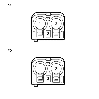
CHECK NO. 3 ANTENNA CORD SUB-ASSEMBLY
-
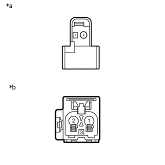
*a
Front view of wire harness connector
(to No.1 Amplifier Antenna Assembly)
*b
Front view of wire harness connector
(to No. 2 Antenna Cord Sub-assembly)
Disconnect the antenna connector from the No. 1 amplifier antenna assembly.
Disconnect the antenna connector from the No. 2 antenna cord sub-assembly.
Measure the resistance according to the value(s) in the table below.
Standard Resistance
Tester Connection
Condition
Specified Condition
2 - 1
Always
Below 1 Ω
1 - 3
Always
Below 1 Ω
2 - Body ground
Always
10 kΩ or higher
1 - Body ground
Always
10 kΩ or higher
Result
Proceed to
OK
NG
-
CHECK NO. 2 ANTENNA CORD SUB-ASSEMBLY
-
*a
Front view of wire harness connector
(to No. 3 Antenna Cord Sub-assembly)
*b
Front view of wire harness connector
(to Antenna Cord Sub-assembly)
Disconnect the antenna connector from the No. 3 antenna cord sub-assembly.
Disconnect the antenna connector from the antenna cord sub-assembly.
Measure the resistance according to the value(s) in the table below.
Standard Resistance
Tester Connection
Condition
Specified Condition
1 - 2
Always
Below 1 Ω
3 - 3
Always
Below 1 Ω
1 - Body ground
Always
10 kΩ or higher
3 - Body ground
Always
10 kΩ or higher
Result
Proceed to
OK
NG
-
CHECK ANTENNA CORD SUB-ASSEMBLY
-
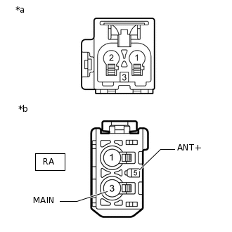
*a
Front view of wire harness connector
(to No. 2 Antenna Cord Sub-assembly)
*b
Front view of wire harness connector
(to Radio and Display Receiver Assembly)
Disconnect the antenna connector from the No. 2 antenna cord sub-assembly.
Disconnect the antenna connector from the radio and display receiver assembly.
Measure the resistance according to the value(s) in the table below.
Standard Resistance
Tester Connection
Condition
Specified Condition
2 - RA-3 (MAIN)
Always
Below 1 Ω
3 - RA-5 (ANT+)
Always
Below 1 Ω
2 - Body ground
Always
10 kΩ or higher
3 - Body ground
Always
10 kΩ or higher
Result
Proceed to
OK
NG
-
CHECK NO. 1 AMPLIFIER ANTENNA ASSEMBLY
Replace the No. 1 amplifier antenna assembly and check if radio broadcasts can be received normally.
OK
Radio broadcasts can be received normally.
Result
Proceed to
OK
NG
OK END (NO. 1 AMPLIFIER ANTENNA ASSEMBLY IS DEFECTIVE)
CHECK NO. 3 ANTENNA CORD SUB-ASSEMBLY
-
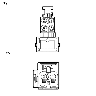
*a
Front view of wire harness connector
(to Satellite Radio Antenna Assembly)
*b
Front view of wire harness connector
(to No. 2 Antenna Cord Sub-assembly)
Disconnect the antenna connector from the Satellite Radio Antenna Assembly.
Disconnect the antenna connector from the No. 2 antenna cord sub-assembly.
Measure the resistance according to the value(s) in the table below.
Standard Resistance
Tester Connection
Condition
Specified Condition
2 - 1
Always
Below 1 Ω
1 - 3
Always
Below 1 Ω
2 - Body ground
Always
10 kΩ or higher
1 - Body ground
Always
10 kΩ or higher
Result
Proceed to
OK
NG
-
CHECK NO. 2 ANTENNA CORD SUB-ASSEMBLY
-
*a
Front view of wire harness connector
(to No. 3 Antenna Cord Sub-assembly)
*b
Front view of wire harness connector
(to Antenna Cord Sub-assembly)
Disconnect the antenna connector from the No. 3 antenna cord sub-assembly.
Disconnect the antenna connector from the antenna cord sub-assembly.
Measure the resistance according to the value(s) in the table below.
Standard Resistance
Tester Connection
Condition
Specified Condition
1 - 2
Always
Below 1 Ω
3 - 3
Always
Below 1 Ω
1 - Body ground
Always
10 kΩ or higher
3 - Body ground
Always
10 kΩ or higher
Result
Proceed to
OK
NG
-
CHECK ANTENNA CORD SUB-ASSEMBLY
-
*a
Front view of wire harness connector
(to No. 2 Antenna Cord Sub-assembly)
*b
Front view of wire harness connector
(to Radio and Display Receiver Assembly)
Disconnect the antenna connector from the No. 2 antenna cord sub-assembly.
Disconnect the antenna connector from the radio and display receiver assembly.
Measure the resistance according to the value(s) in the table below.
Standard Resistance
Tester Connection
Condition
Specified Condition
2 - RA-3 (MAIN)
Always
Below 1 Ω
3 - RA-5 (ANT+)
Always
Below 1 Ω
2 - Body ground
Always
10 kΩ or higher
3 - Body ground
Always
10 kΩ or higher
Result
Proceed to
OK
NG
-
CHECK SATELLITE RADIO ANTENNA ASSEMBLY
Replace the satellite radio antenna assembly and check if radio broadcasts can be received normally.
OK
Radio broadcasts can be received normally.
Result
Proceed to
OK
NG
OK END (SATELLITE RADIO ANTENNA ASSEMBLY IS DEFECTIVE)