ROOM TEMPERATURE SENSOR (for Automatic Air Conditioning System) INSPECTION
-
INSPECT COOLER THERMISTOR
-
Measure the resistance according to the value(s) in the table below.
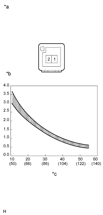
Standard Resistance Tester Connection Condition Specified Condition 1 - 2 10°C (50°F) 3.00 to 3.73 kΩ 15°C (59°F) 2.45 to 2.88 kΩ 20°C (68°F) 1.95 to 2.30 kΩ 25°C (77°F) 1.60 to 1.80 kΩ 30°C (86°F) 1.28 to 1.47 kΩ 35°C (95°F) 1.00 to 1.22 kΩ 40°C (104°F) 0.80 to 1.00 kΩ 45°C (113°F) 0.65 to 0.85 kΩ 50°C (122°F) 0.50 to 0.70 kΩ 55°C (131°F) 0.44 to 0.60 kΩ 60°C (140°F) 0.36 to 0.50 kΩ Note
-
Touching the sensor even slightly may change the resistance value. Hold the connector of the sensor.
-
When measuring the resistance, the sensor temperature must be the same as the ambient temperature.
Tech Tips
As the temperature increases, the resistance decreases (refer to the graph).
If the result is not as specified, replace the cooler thermistor (room temperature sensor).
Text in Illustration *a Component without harness connected
(Cooler Thermistor (Room Temperature Sensor))
*b Resistance kΩ *c Temperature °C (°F) -
-