CYLINDER HEAD REPAIR

PROCEDURE
-
REPAIR INTAKE VALVE SEATS
Note
-
Repair the seat while checking the seating position.
-
Releasing the seat cutter pressure gradually helps to make the intake valve seat faces smoother.
-
Using a 45° cutter, resurface the valve seat so that the valve seat width is more than the specification.
-
Hand-lap the valve and valve seat with an abrasive compound.
-
Check the valve seating position.
Tech Tips
This procedure is necessary to select a cutter to be used in the following steps.
-
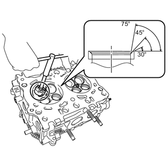
Using 30° or 75° cutters, correct the valve seat so that the contact condition between the valve and valve seat is within the standard.
Note
-
Repair the seat while checking the seating position.
-
Releasing the seat cutter pressure gradually helps to make the intake valve seat faces smoother.
Tech Tips
Select an appropriate cutter by referring to the following chart.
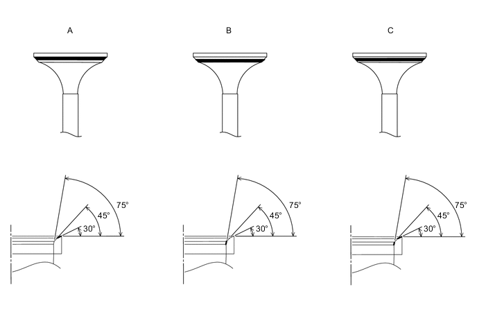
Contact position Cutter to be selected A in the illustration If the valve face position is high, use a 30° valve seat cutter in order to grind the surface so that the contact surface between the valve and the valve seat is at a standard value. B in the illustration If the valve face position is low, use a 75° valve seat cutter in order to grind the surface so that the contact surface between the valve and the valve seat is at a standard value. C in the illustration If the valve face position is centered, use a 30°and 75° valve seat cutter in order to grind the surface so that the contact surface between the valve and the valve seat is at a standard value. -
-
Hand-lap the valve and valve seat with an abrasive compound.
-
-
REPAIR EXHAUST VALVE SEATS
Note
-
Repair the seat while checking the seating position.
-
Releasing the seat cutter pressure gradually helps to make the intake valve seat faces smoother.
-
Using a 45° cutter, resurface the valve seat so that the valve seat width is more than the specification.
-
Hand-lap the valve and valve seat with an abrasive compound.
-
Check the valve seating position.
Tech Tips
This procedure is necessary to select a cutter to be used in the following steps.
-
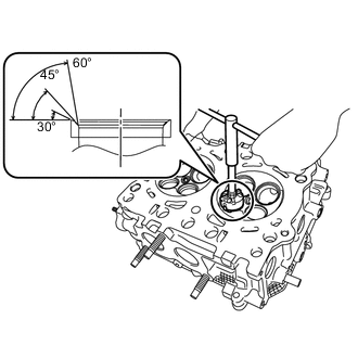
Using 30° or 60° cutters, correct the valve seat so that the contact condition between the valve and valve seat is within the standard.
Note
-
Repair the seat while checking the seating position.
-
Releasing the seat cutter pressure gradually helps to make the intake valve seat faces smoother.
Tech Tips
Select an appropriate cutter by referring to the following chart.
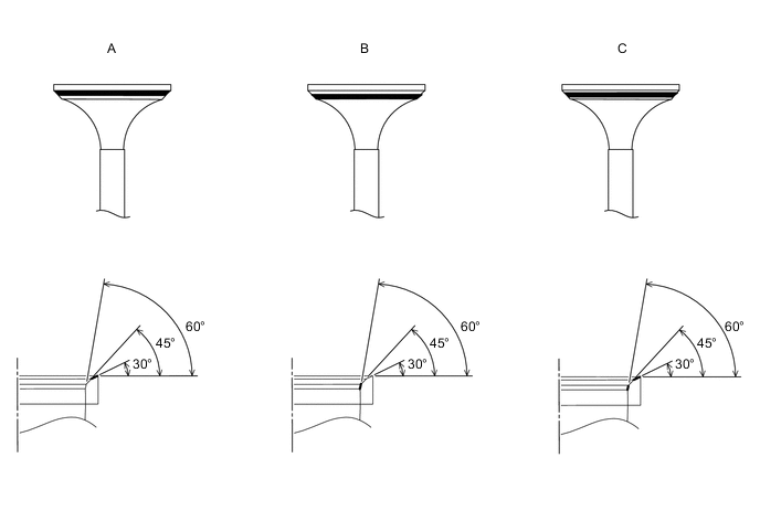
Contact position Cutter to be selected A in the illustration If the valve face position is high, use a 30° valve seat cutter in order to grind the surface so that the contact surface between the valve and the valve seat is at a standard value. B in the illustration If the valve face position is low, use a 60° valve seat cutter in order to grind the surface so that the contact surface between the valve and the valve seat is at a standard value. C in the illustration If the valve face position is centered, use a 30°and 60° valve seat cutter in order to grind the surface so that the contact surface between the valve and the valve seat is at a standard value. -
-
Hand-lap the valve and valve seat with an abrasive compound.
-
-
REPAIR VALVE
-
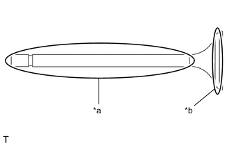
Text in Illustration *a Valve stem *b Valve face Apply a light layer of engine oil to the valve stem, and a small amount of an abrasive compound uniformly to the valve face.
Tech Tips
-
Do not apply the abrasive compound more than necessary.
-
Do not apply the abrasive compound to the valve stem as the valve stem may be affected.
-
-
Slowly insert the valve stem into the valve guide bush and lap the valve and valve seat.
Tech Tips
-
Lift the valve and strike the valve on the valve seat 2 times, and slightly rotate the valve. Repeat this set.
-
The contact surface between the valve and the valve seat may become larger than the standard value, therefore, ensure that the valve is not continuously lapped by rotating while seated in the valve seat.
-
While lapping, ensure that the valve is not removed from the valve guide bush by lifting too much.
-
-
After lapping, completely remove the abrasive compound.
Note
Be sure to completely remove the abrasive compound as the remained compound could cause engine troubles.
-
Check the valve seating position and width.
-